- Computers
- Steel
Desk 2 (and spare bedroom)
A while ago (well, about 8 years ago!), I made a desk to hold my computer, Kurzweil keyboard and two 21" CRT monitors. This was in the spare bedroom, but I had a few of problems in using it.
- The desk was very close to the bed, which meant the right hand side was pretty much off-limits. This is where the mixing desk lived.
- The keyboard was on the upper deck, which was a difficult place to type from.
- It was in the spare room, which is a little bit out of the way, and I found myself watching TV rather than doing work on the computer.
So, I decided to move all the computer equipment to the dining room - and ended up with some old desks that our office were giving away when we moved. The spare bedroom did contain a bed, albeit covered with stuff, and the desk became my electronics station.
This was all well and good until Marise, my girlfriend, moved in. She wanted a dining room with a dining room table - I told her that we couldn't have one until the spare room had been finished so I had somewhere to put it.
I'd started the front room in around 2006, but started building my Aeon GT3 instead. The original plan was to fit a shower, basin and toilet in the room, but when demolishing some partition walls, my brother accidentally chipped the shower tray - in addition, adding a shower would've taken quite a bit of space away from the room itself.
After discussing the options with Marise, I came up with a plan as to how the room could be arranged. Her requirements were:
- A wardrobe to contain boxes full of miscellaneous crap we'd accumulated (it's not aimed at visitors!)
- A bed
- Everything else to be as small as possible
My requirements were:
- Toilet and basin
- A bed
- A two-tier desk for my computers, music gear and electronic components
- Two chairs for use with the desk
The toilet, basin, chairs and bed were already purchased - just not fitted. The doors for the wardrobe were the old ones for the main bedroom (in 2011, I made some fitted wardrobes, and the old doors were spare). Everything else was new.
In order to minimise the desk's footprint, I decided that there needed to be a pull-out section which would hold the keyboard and mouse (and anything else that could fit, like my Shuttle Xpress).
Using Xara Xtreme, I did a quick plan view of the room, and moved things around until I found something that fitted.
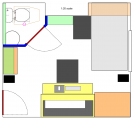
I've not made any key for this, but basically red is a door, blue is a new partition wall, green is a shelf, orange is a cupboard or wardrobe, light grey is the bed, dark grey is a chair, black is a speaker, and yellow is the desk. The objects such as chairs are rough outlines; the cupboards, walls and doors are real sizes.
At the end of May 2012, I started on the room, and mid-June, it was time to start designing the desk structure (having built the partition walls and the wardrobe).
Since the desk was going to be my main focus, I wanted something that would look good, and be strong. I opted for Oak from www.WoodWorktops.com, and to keep costs down, a single 4m length of 650x32mm. This would give me:
- Two decks of 1500x650mm
- Two other sections of 1000x325mm
Originally, I was looking at having a swivelling keyboard section, which would move under the desk, but when in use, would maintain the same level of the bottom deck, and make it look like a single piece of wood. I made a model out of Lego:
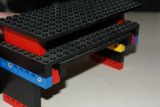
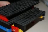
While I could've made this, it would be a fairly complex thing to make for the limited number of times it would be needed, so I dropped this plan, and opted for a sliding keyboard extension instead. These slides I got from Screwfix Direct.
Another plan I dropped was to make the desk a floating desk - where it was only attached to the wall, and no legs. I wasn't too sure about how many screws I would need in the wall (some of the house bricks are quite brittle, but some of them are quite hard).
So after a trip to B&Q, I decided to use some legs that they sell, but make them unboltable, so I could remove them if the desk needed to be transported.
Using Lightwave 11, I came up with a rough idea for the frame. This allowed me to measure some of the dimensions that would be crucial, such as the height of the keyboard extension - which should be as close to my current desk height as possible.
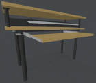
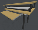
When the wood turned up, I was very pleased with it - and it looks incredibly strong - so I probably won't make a frame for the top section (it doesn't need to hold quite as much as the bottom section).
Saturday 23rd June, I started to make the frame.
I had an old desk top that was beginning to become a bit damp, but was flat enough, and near to the dimensions that I needed. This was 1300x670mm - and the real top would be 1500x650. I would make the frame fit this, with a slight inset for the legs. The first job was to mark the 650mm width that would give the width limit.

I then marked the intended leg positions. They would go right to the edges of this desk top, and 20mm inset from the width. I also marked the sliding section (in pencil), and decided which was the front, and which was the back.

I collected the steel I was going to use for this - which came from two sources. The first was from my first attempt at a CNC machine, which was 25x50mm box section, and the second was left over bits from my friend's Marcos Mantula when we repaired the frame, which was 40mm square box section.

I then got out my old chop saw (which I hadn't used for quite a while - but I did clean it a two years ago, when I found that it had filled with rain water, replacing the cutting oil), and cut the two sides.

A length of 40mm box was cut to go down the middle - or, more accurately, one edge would go down the middle, which was the extent of the sliding section.
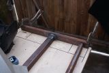
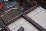
I'd cut the back section before the central brace, but for some reason I'd accidentally measured it about 17mm too short - so I cut another small section to make it a bit longer. This is one of the reasons why I like working in steel - it's a lot easier to correct mistakes like this than in wood.

Next, I needed two support the legs with a bit more steel, and also provide a support for the sliding frame. This was done with a bit more 40mm box section and also some more 25x50mm box. The legs will only be bolted down with three bolts - which should be enough (I hope!)
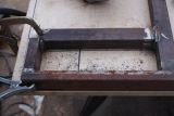
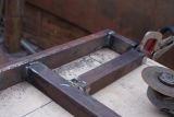
And then it was time to look at how to mount the slide extension. Since this measurement was a little critical, I decided to use the bit of wood that had been cut for me - I don't really like bringing in 'live' objects into the welding arena, but it was necessary. This is how it would be mounted:

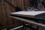
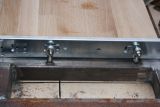
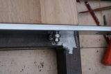
I'd not worked out how to mount this in the computer models, so I had a lot of head-scratching to figure the best way of doing this. I eventually opted for something that I'd done on the first CNC machine - namely some 6mm bearings screwed into the 40mm box section. This would allow me to have some adjustment for the height of the sliding section, and also had allowed a small amount of horizontal adjustment (with washers), and the Z - plane could be a little out if I'd not drilled the holes in the right place. The only downside is that as the 40mm box is 2.5mm thick, it only leaves 2.5 turns for the thread. If it becomes a problem, then I can replace them with rivnuts (which I've still got a fair number left over from my Aeon).
The sliding section can come quite far forward:
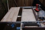
And that was the frame pretty much done - just flattening some of the welds, and drilling the holes for the leg bolts (they'll be tapped after painting):

And finally, using a zip-wheel to remove most of the rust that would be visible after painting (I'll be using black Hammerite, which can be painted over rust anyway, but it'll be nice to get it clean):

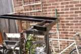
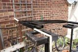
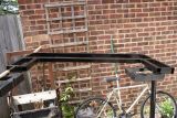
Sunday 24th June, I painted it - it was a nice sunny day (for once!), and the paint dried fairly quickly.
