- Eagle PCB
- Electronics
- Mains electricity
- Microchip PIC
- Schematics
USB Switch (3rd version)

USB switch by Jason Tribbeck is licensed under a Creative Commons Attribution 3.0 Unported License.
The problem
After a week or so of using it, I came to the computer after it had been turned off overnight, and found that the monitors and stuff were still turned on - even though both computers were off. Disconnecting the USB connectors confirmed what I had suspected: the relays were stuck on - just like the prototype version.
The solution
I'd bought some solid-state relays before Christmas, for a different project (more details to come - once I've built it!). I had contemplated using them for the revision G board, but as I had the other relays, I wanted simplicity instead.
The solid state relays I've got are Sharp S202S02 relays. They're optically driven zero-point switching relays, capable of driving 8A - although it may need some cooling to do this. The data sheet also recommends a snubber - but I can't decide what type of snubber I need, so I'll leave it for the time being.
The new circuit
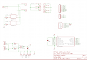
This is pretty similar to the old circuit - except there's no driving transistors for the solid-state relay as the PIC can drive LEDs directly.
The PCB
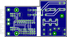
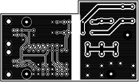
This is a slighly redesigned PCB, and it's now L-shaped to allow a bit more space for the spade terminals (it was a bit of a tight squeeze). The four mounting holes are in exactly the same place, so I don't need to drill any new holes in the case. And the PCB under the USB sockets has been shortened, so I don't need to use quite so much PCB material.
IMPORTANT!
In this design, I'd put a filled area for the earth on the mains side. THIS SHOULD BE REMOVED because it means you end up with a potential for a spark to jump the tracks. Alternatively, you can increase the isolation of the copper pour area.
In addition, I would cut a slot between the low-voltage and the high-voltage sections underneath the relays to provide even more of a gap (as it stands, it should be okay - but if moisture gets into the PCB, then a spark could jump the gap. With an air gap this is less likely).
My next version (which I've not documented yet) incorporated both of these. I'll do a write-up later...
Eagle PCB files
I had forgotten to provide them for the revision G board - but for this version you can download them. Note that I use Eagle PCB version 6, which uses XML as its format. If you are using versions prior to 6, you will not be able to read them. I won't be making version 5 (or even 4) PCBs, so if you want it - tough - you'll need to transcribe it from the PDFs.
The box
As I'd used exactly the same hole locations on the PCB, I was able to re-use the box.
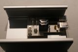


This is the board in the case. The L-shaped board allows the spade connectors to go past the PCB, whilst allowing a bit more space between the ones fitted on the PCB itself.
Testing it is a bit more difficult as you can't hear the relays click. However, I did find a change with the continuity tester between the switched live and the live feed when the board was on and off; a quick continuity test of the other signals showed me that it was working as expected (nothing untoward shorted), so I tried a live test - this went okay.
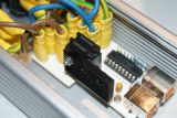
I ran it for about 20 minutes with the cover off to make sure that it didn't get too hot. It didn't seem to, although it was slightly warm. Just in case, I bolted an IC heatsink to the relays, and put the cover on it.
This is the heatsink I used. It's designed for a 28-pin DIL chip, and all I did was drill three 3mm holes in it (so I could decide the best orientation for the heatsink).
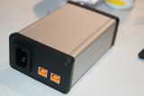
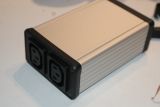
And with the case screwed up, it looks identical to the revision G board.
The code
The code is identical to the old code - in fact, as I'd socketed the PIC, I just pulled it out and transferred it.
Does it work?
One thing I won't be able to do is see how it performs over time - as the revision G board stopped working within a week, I'll leave it a month before reporting its success!
Well, it's been over a month since I made it, and it's still working fine. So I'm very happy with it.
And now it's been two years since I made it, and it's still going strong. The only reason why I may re-make it is to remove the copper pour area.
And as I've been refreshing the website, copying all the data over, it's still working after 6+ years. The S202S02 is no longer available from Farnell though, so if anything does go wrong, I'll probably have to go back to relays...
Parts
If you want to make one, you'll need the following parts:
- 2x USB-B standard ports (Farnell 1308876, although I used 1753809, which is a high-retention part)
- 1x Microchip PIC16F628A (Farnell 9760423)
- 2x Sharp S202S02 solid-state relays (Farnell 1618475)
- 1x Case (Farnell 4272857, although I used 4272973 which has plastic sides instead of aluminium). This is a bit of a matter of personal choice, but you won't be able to go much smaller than this.
- 2x 1N4148 diodes (Farnell 1081177)
- 3x 100K ¼W resistors (Farnell 9339078)
- 2x 390R ¼W resistors (Farnell 9341846)
- 1x 100nF capacitor (Farnell 9750878)
- 1x 10µF Tantalum capacitor (Farnell 1753974)
- 10x 6.3mm spade terminals (Farnell 488343)
- 2x Schurter 6600.4315 IEC outlet (Farnell 1176793 - you may need different parts depending on the thickness of the panel)
- 1x Schurter 6100.4215 IEC inlet (Farnell 2080455 - you may need different parts depending on the thickness of the panel)
- 1x 36-way pin header (Farnell 1822166 - used for extension, UART and PIC programming interface
Note that you can change these parts for any equivalent. You can also use an IC socket for the PIC if you want (I always use turned-pin sockets for reliability).

