- Eagle PCB
- Electronics
- Mains electricity
- Microchip PIC
- Schematics
- Source code
USB Switch

USB switch by Jason Tribbeck is licensed under a Creative Commons Attribution 3.0 Unported License.
This is a project that I've been working on for a few months - mostly off than on though!
The idea is to basically save me money by reducing my quiescent electricity usage. When I had my computers downstairs, when shutting down, I would turn everything off - or rather, put everything on standby. What I wanted was something that would automatically turn everything on when either of my two computers turned on, and also turned everything off - preferfably using as little current as possible.
It all came to a head when I bought a 7-port USB hub for the Mac - this would leave itself powered on if either the external PSU or the Mac was switched on. I didn't want to have peripherals powered up when the computer wasn't in use, and I also didn't want the computer being the only source of power.
The equipment that I only wanted on when the computer was on was:
- Two Dell 2407 monitors
- 7-port USB hub
- Printer
- Amplifier
- External hard drive
I happen to own an APC power unit, which has a TCP/IP stack and a web interface which I've used with my synthesizers for a number of years, but this is a little impractical as it would need a web request to turn the equipment on.
When I moved everything upstairs, I made the first prototype of what I wanted. It had a single IEC inlet, and twin IEC outlets, a switch, a bi-colour LED, and a 9-pin D-type socket for expansion. The unit was powered by USB, and had two USB inlets - one for each computer. If either of them turned on, then the IEC outlets would be switched on, with a small gap between them. The switch was to allow me to have a second USB port from each computer, and allow a USB outlet to switch, so if the Mac was on, the peripherals were connected to the Mac; if the PC was on (but not the Mac), then they would be connected to the PC. The switch would allow me to manually transition if I had both on at the same time and I needed the peripherals on the other computer.
This was generally okay, but there were a few problems with it:
- Both relays would occasionally latch on - they aren't latching relays, so I had no idea how this would happen. To ensure that they were turned off, I had to hit the box against something hard.
- I never got around to making the USB peripheral board (I did etch it; it was part of the main board), so the switch and LED were redundant.
- I never got around to making any extensions which needed the 9-pin D-type connector
- The case was a very tight fit, and not having a front panel didn't help. Getting the holes cut into aluminium was going to be a pain, so I didn't get around to it.
So I decided that a new version was to be made, and using some of the agile development philosophies we have at work, I did the minimum needed to get it working (although with a small view to future expansion in mind).
And since I would imagine that other people may want to make it, instead of my usual 0603 SMT components, I used through-hole for everything - and also a PIC16F628A microcontroller I had kicking around (the previous one was a PIC16F1516).
The design
As mentioned, the heart of the unit is a PIC16F628A microcontroller. If you don't want any expansion capabilities, then you can use quite a few other PICs - although the easiest would be a PIC16F627A (which is the same, albeit with a smaller flash memory size).
Only the power and ground pins from the two USB ports are used - you can make a single port version if you want (or even a more-than-two port, but that would require some rework).
The PIC drives two relays (via transistors), and these can switch up to 6A each. There is a delay of a second or so between each output turning on in order to reduce the inrush current when things turn on.
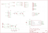
The PDF is arranged in several chunks. From top-left, going clockwise:
- Live power (switched through relays)
- Netural power
- Earth
- Expansion port 1 (additional relays)
- Expansion port 2 (UART)
- PIC ICSP socket (PicKit2/3 compatible)
- PIC
- USB inlets
- Relay coils
- (Centre) relay drivers
How it works
The power from two USB pins are connected to eact other via D1 and D2. This means that the +5v power supply is provided when either USB port is connected (although it's not actually +5V, as some voltage is lost from the diodes - but it's good enough for the circuit). The USB grounds are connected to each other. This should be fine, although you could be creating a ground loop (it's never affected anything I've done yet).
In addition, each USB power is pulled low via R2 and R3 (100K resistors), and these are fed into the PIC, so it can determine which computer is on.
When the PIC powers up, it turns all the pins off, and then pauses for a bit, turns on RLD1, pauses a bit, turns on RLD2 and so forth until all the pins are on. RLD3 to RLD8 are available from the 8-pin expansion header SV1.
Q1 and Q2 are transistor drivers for the relays (the PIC can't handle the load of a relay itself, so needs a bit of help), and D3 and D4 provide back-EMF protection for the transistors.
SV2 is a simple 4-pin plug, and this can be used for a simple UART - if you want to talk to it (for example, you could make it switch power via a manual method - I would be looking at this for my synthesizers, so when I want to write music, I can tell it to turn them on; otherwise they're off).
All the mains wiring are connected on the PCB via PCB-mounted spade terminals, so you don't need to double-up wires into the spade connectors. Three neutral and three live terminals are available, and four earth spades are present, so the case can have its own wire.
There really isn't that much to it!
If you don't need to have more than 2 relays, then you can simply omit SV1 and SV2.
The PCB
The PCB is designed to be fairly small (I've used a small box to hold it), and is split into two areas.
Looking from the component side, the left hand side is the digital circuitry, and the right hand side is the mains circuitry. There is a 5mm gap between the two sections, to prevent the possibility of stray connectivity between the two. There are 4 mounting holes (using 2.5mm screws), and these are connected to the earth. This provides a connection to the earth to the case (in addition to the 4th earth spade terminal).
There is a slight break to the isolation rule in that the two mounting screws on the left hand side are connected to earth with a small isolation around the bolt. I've measured the spacers I'm using, and they're 4.5mm in diameter, so I've made the vias 5mm.
The code
I wrote the code with no power connected - I told the PicKit3 to power the circuit, and that also gave me a test mode: if neither USB port was powered, then it's being powered externally; as a result, it'll repeat the power on cycle ad-infinitum.
This was written using the free version of Microchip's XC8 compiler, with MPLAB-X (which works really nicely on the Mac).
#include <xc.h>

#pragma config CP = OFF
#pragma config CPD = OFF
#pragma config LVP = OFF
#pragma config BOREN = ON
#pragma config MCLRE = ON
#pragma config PWRTE = ON
#pragma config WDTE = OFF
#pragma config FOSC = INTOSCIO

#define VP2   (PORTAbits.RA2)
#define VP1   (PORTAbits.RA3)
#define RLD1  (PORTBbits.RB4)
#define RLD2  (PORTBbits.RB5)
#define RLD3  (PORTBbits.RB6)
#define RLD4  (PORTBbits.RB7)
#define RLD5  (PORTAbits.RA6)
#define RLD6  (PORTAbits.RA7)
#define RLD7  (PORTAbits.RA0)
#define RLD8  (PORTAbits.RA1)
#define AUX   (PORTBbits.RB3)

void delay(void)
{
  unsigned int i;
  for(i = 1; i != 0; i++);
  for(i = 1; i != 0; i++);
  AUX = !AUX;
}

int main(int argc, char** argv)
{
  TRISA = 0x3c; // RA0-1,6-7 = O; RA2-5 = I
  TRISB = 0x07; // RB0-2 = I; RB3-7 = O
  CMCON = 0x07;
  do
  {
    PORTA = 0x00;
    PORTB = 0x00;
    delay();
    RLD1 = 1;
    delay();
    RLD2 = 1;
    delay();
    RLD3 = 1;
    delay();
    RLD4 = 1;
    delay();
    RLD5 = 1;
    delay();
    RLD6 = 1;
    delay();
    RLD7 = 1;
    delay();
    RLD8 = 1;
    delay();
  } while((VP1 == 0) && (VP2 == 0));

  do
  {
  } while(1);
}
Making the box
The board is free-standing, so in order to make it secure, I needed to drill holes in the case. To reduce the amount protuding from the underside of the case, I drilled it to 2mm, and then tapped it using a 2.5mm tap. You can just drill it to 2.5mm, and then either use the bolt upside down, or a nut at the bottom.
In order to get the right position, I printed a 1:1 scale print out with just the hole positions marked, and drilled into the hole positions. This was good enough - and although I've used stainless steel bolts with an aluminium case, I'm not that worried about not being able to unbolt it in the future (stainless steel and aluminium react with each other).
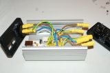
This is the view of the case with the lid off, and the inlet side populated:


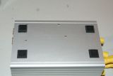
And the underside showing the bolts producing slightly:
The outlet side I had a little trouble with cutting the holes to the right size (they were a little too big), so some hot-melt glue holds them in place.

And with it all assembled:
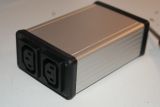
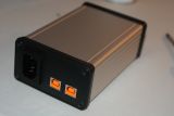
And, not surprisingly, it works fine.
Parts
If you want to make one, you'll need the following parts:
- 2x USB-B standard ports (Farnell 1308876, although I used 1753809, which is a high-retention part)
- 1x Microchip PIC16F628A (Farnell 9760423)
- 2x V23092-A1905-A302 relays (Farnell 1175047, although I used 1169338, which is SPCO instead of SPNO and a different manufacturer, because I had them available)
- 2x BC547B transistors (Farnell 1574381)
- 1x Case (Farnell 4272857, although I used 4272973 which has plastic sides instead of aluminium). This is a bit of a matter of personal choice, but you won't be able to go much smaller than this.
- 4x 1N4148 diodes (Farnell 1081177)
- 3x 100K ¼W resistors (Farnell 9339078)
- 2x 1K ¼W resistors (Farnell 9339051)
- 1x 100nF capacitor (Farnell 9750878)
- 1x 10µF Tantalum capacitor (Farnell 1753974)
- 10x 6.3mm spade terminals (Farnell 488343)
- 2x Schurter 6600.4315 IEC outlet (Farnell 1176793 - you may need different parts depending on the thickness of the panel)
- 1x Schurter 6100.4215 IEC inlet (Farnell 2080455 - you may need different parts depending on the thickness of the panel)
- 1x 36-way pin header (Farnell 1822166 - used for extension, UART and PIC programming interface
Note that you can change these parts for any equivalent. You can also use an IC socket for the PIC if you want (I always use turned-pin sockets for reliability).

