- Home
- 3D printing
- Cars
- Cats
- CNC machines
- Computers
- Electronics
- Lightwave
- Miscellaneous
- Music
- Software
- Steel
- Active project
- Altium ECAD
- Electronics
- Software
Extensions
Since working on the original code, I've added some extensions to it.
Outline milling
I've added the ability for it to mill the outline (and any inside bits) of the board. Luckily, Altium has an option to generate the mill pattern from the board outline, and this is used to make sure it is able to follow the path. This required the addition of decoding arcs in the Gerber files (to allow for the curved parts), and I've been able to make some nice shapes.
It will perform a 5-level mill of the outline, reversing the direction each time, and also randomising from a different start point in order to reduce the tendency for the milling bit to bend while milling (I suspect the spindle isn't going fast enough - luckily my new CNC machine's spindle will run about 6 times faster).

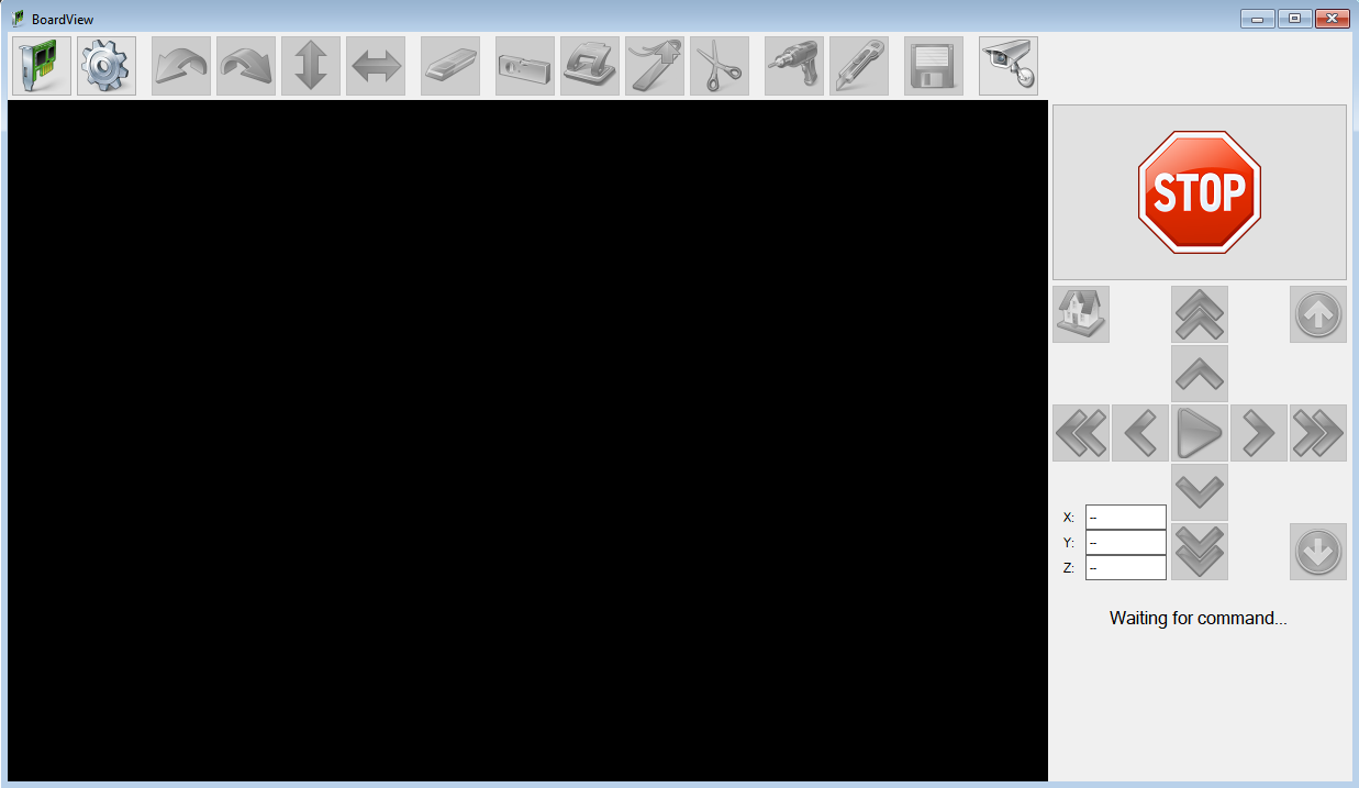
The icons along the top have been extended, and (for a complete list) are as follows:
- Load Gerbers
- Settings
- Rotate left
- Rotate right
- Flip vertically
- Flip horizontally
- Erase everything
- Calibrate positions
- Drill test hole ('stamp')
- Mark position
- Remove section from milling (used to prevent it from cutting into the tool holders)
- Drill holes
- Mill outline
- Save current workspace (experimental)
- Open camera
Manual pick and place guide
While this isn't actually part of the main software, I've reused a few components from it to make a guide to assist me place components using my manual pick-and-place machine.
The components it reuses are:
- Gerber parsing
- Optimal route finding
The Gerber parsing is used to read the holes as well as the outline of the board, so I can present it to the user. This is combined with the Altium's pick and place output to draw the components.
The optimal route finding is used to navigate a path placing components that are near to each other, so it's easier to find the next one to place.

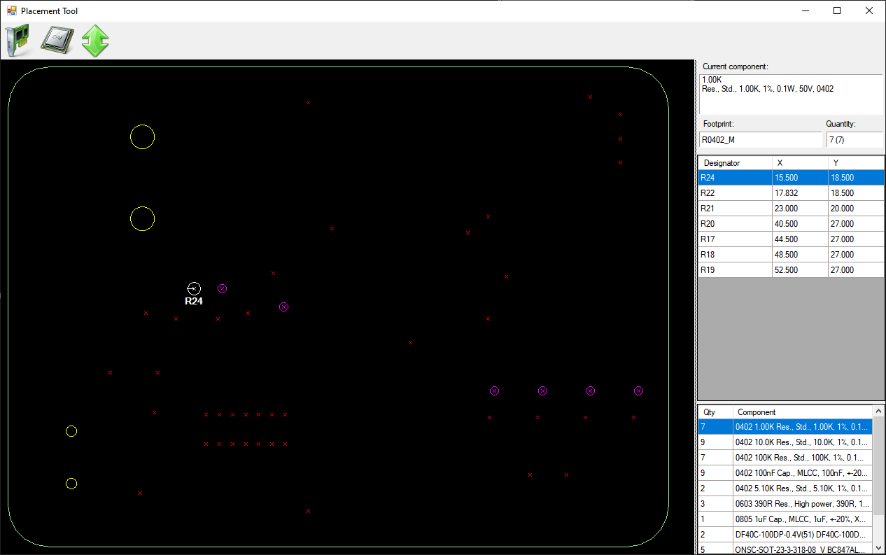
- To the left is the PCB - in this case, it's a small board, and R24 is being requested to be placed. Purple crosses with circles are components that are due to be placed now, and red crosses are other components. When placed, they go blue.
- To the top right is the list of components that need to be placed now (with a description at the top)
- To the bottom right is the whole list of components, ordered by size (smallest to largest) - if the size can be determined. Otherwise it's alphabetical
The software does know about the top and bottom of the board, but it doesn't know about through-hole components.
When the software starts up and a board loaded, it will use text-to-speech to read out the component description, and then the first designator. Pressing 'space' moves on to the next designator (which it will read out). Pressing 'n' will skip all the designators in this component batch.
The text-to-speech was added because I got a new pair of magnifying glasses that made it much harder to see the screen clearly!
