
Assembly part 4
Alignment
I bought a digital angle gauge (I had an old analogue one which was definitely very dated and difficult to read), and zeroed it on the bed.
I then went around and measured the relative angles of various parts of the machine.
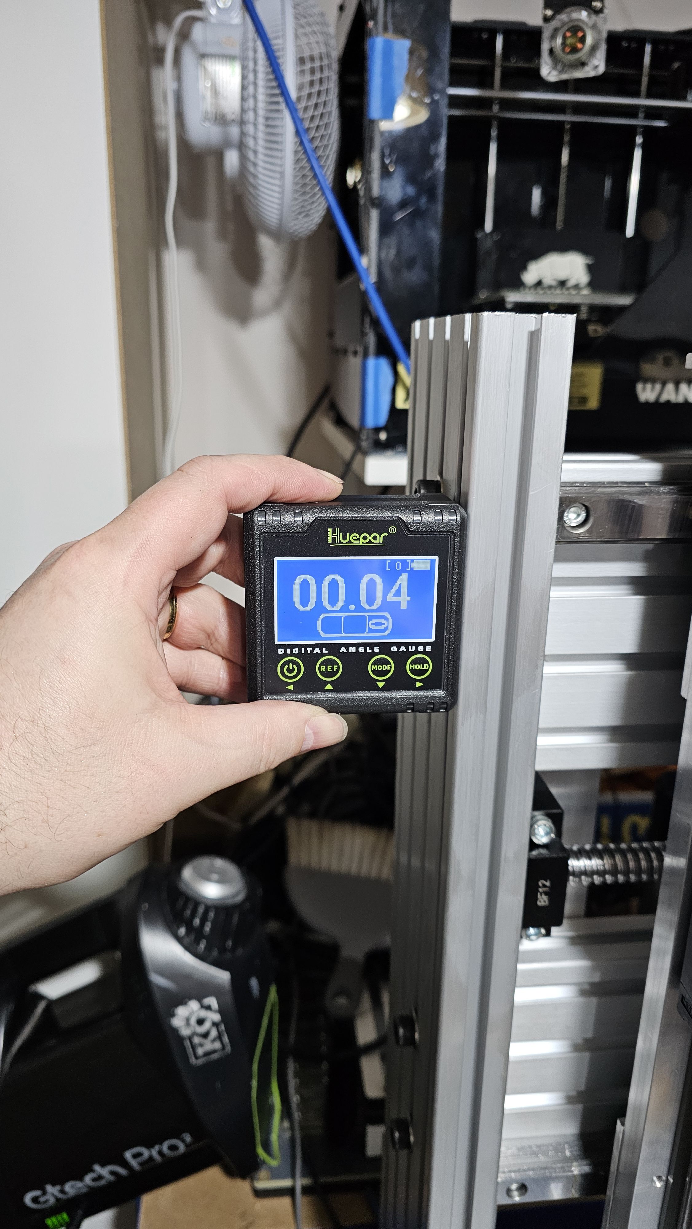
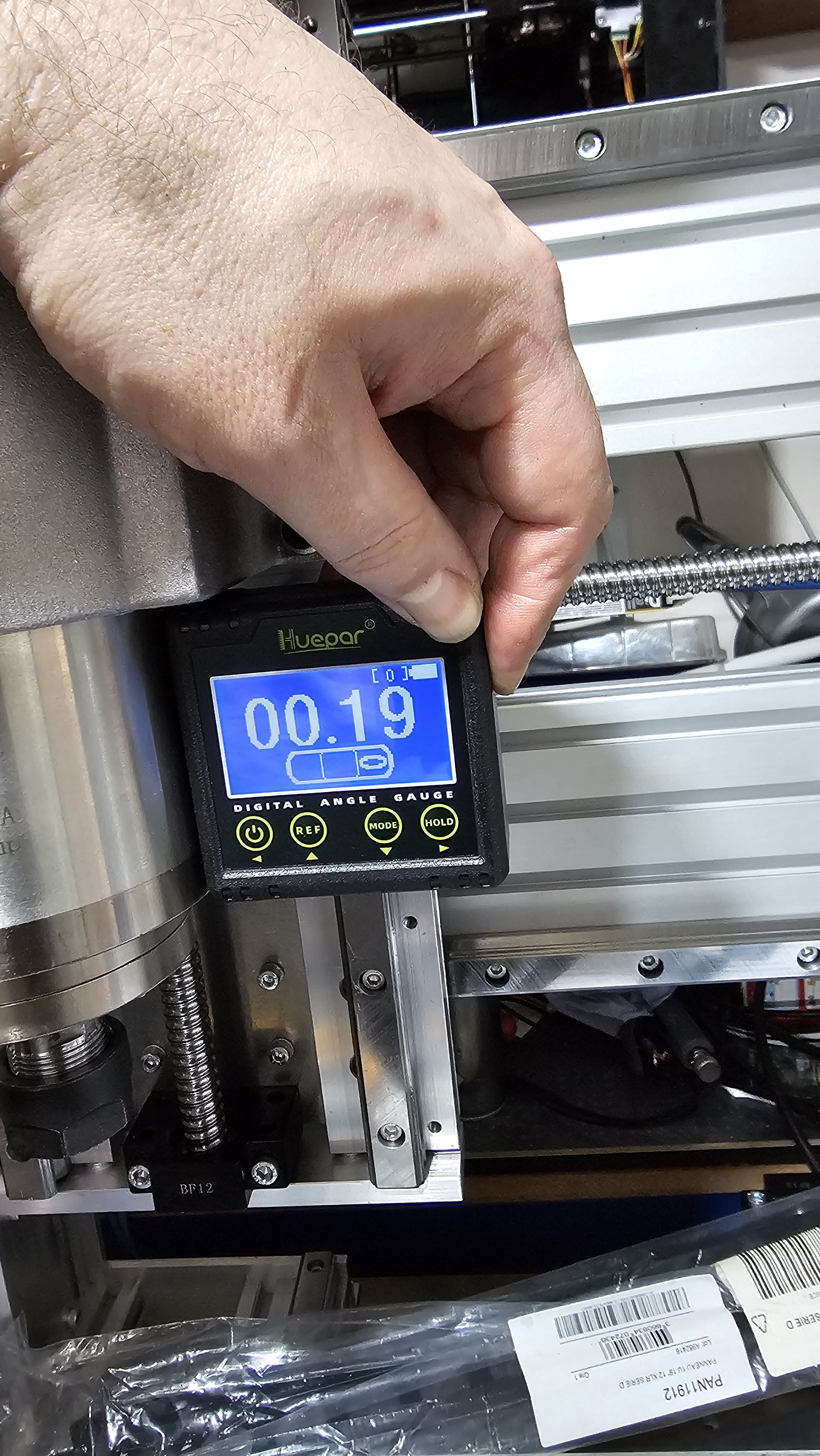
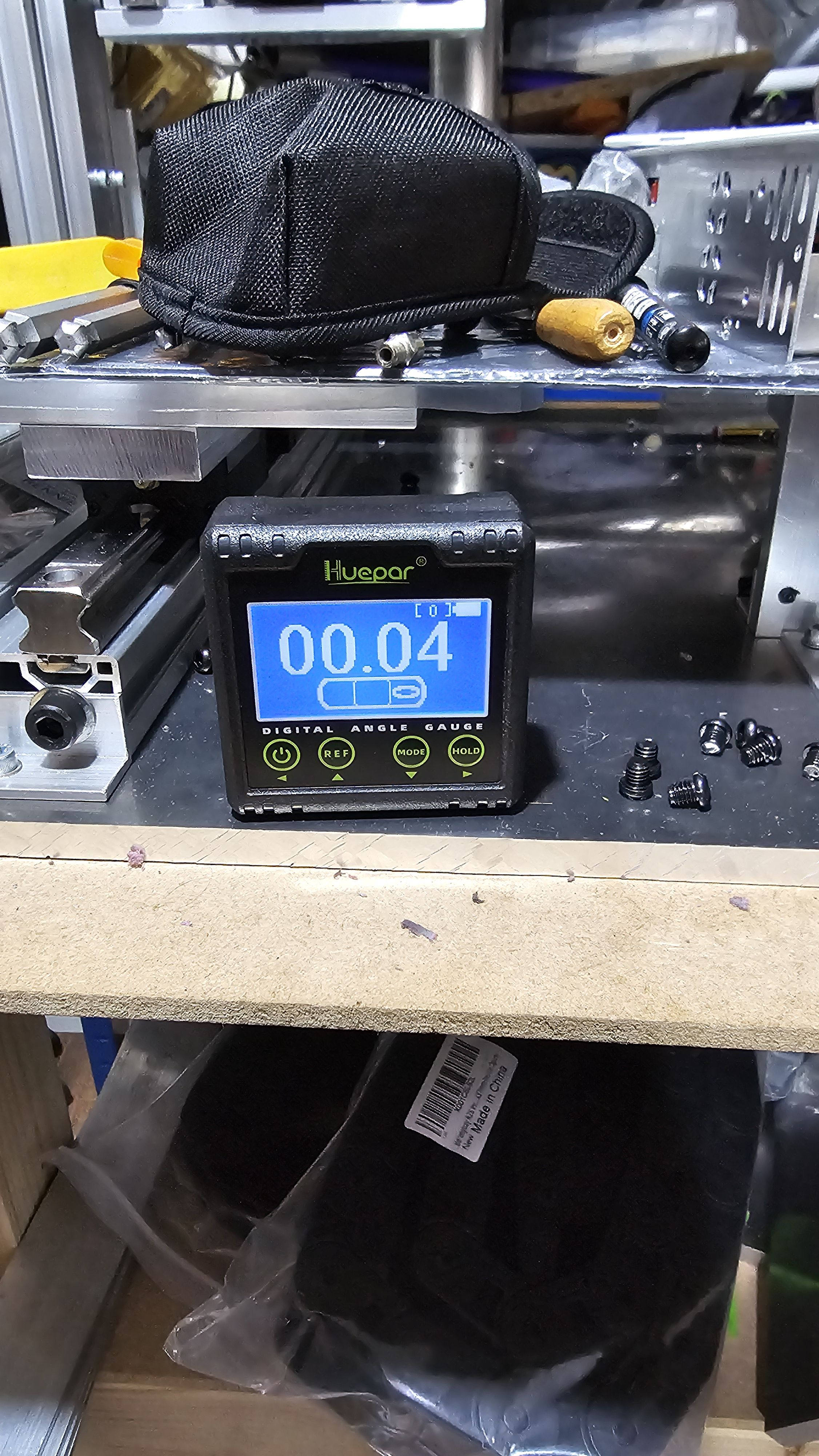
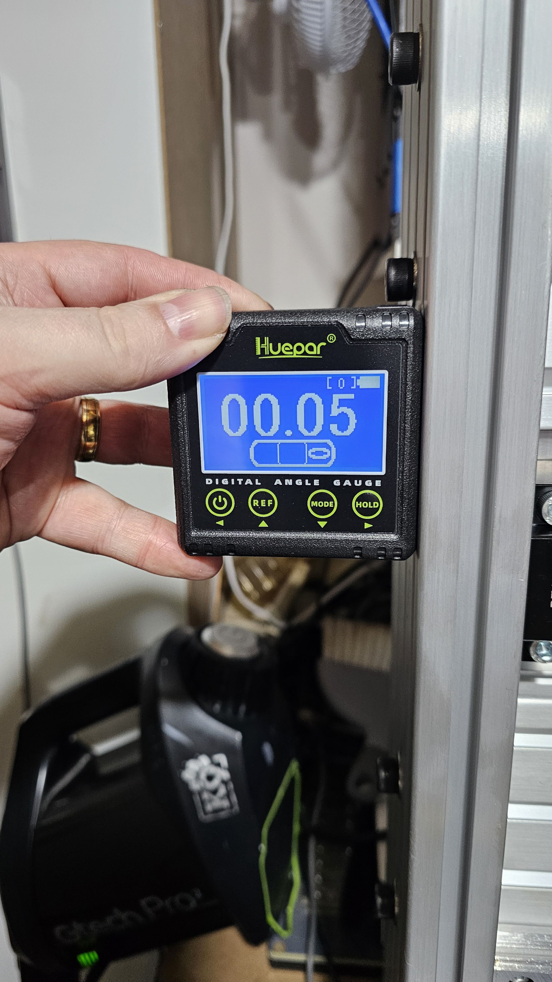
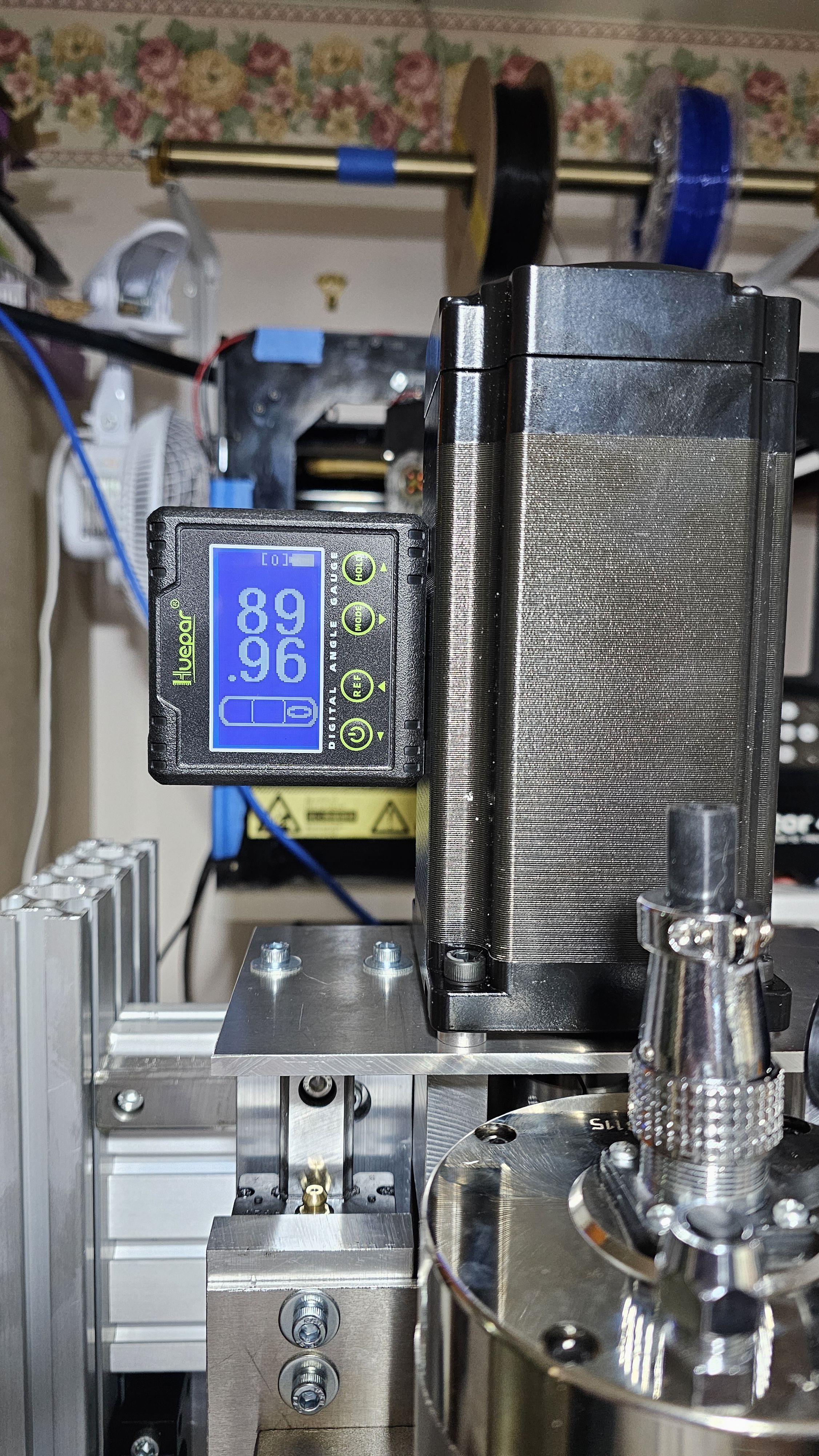
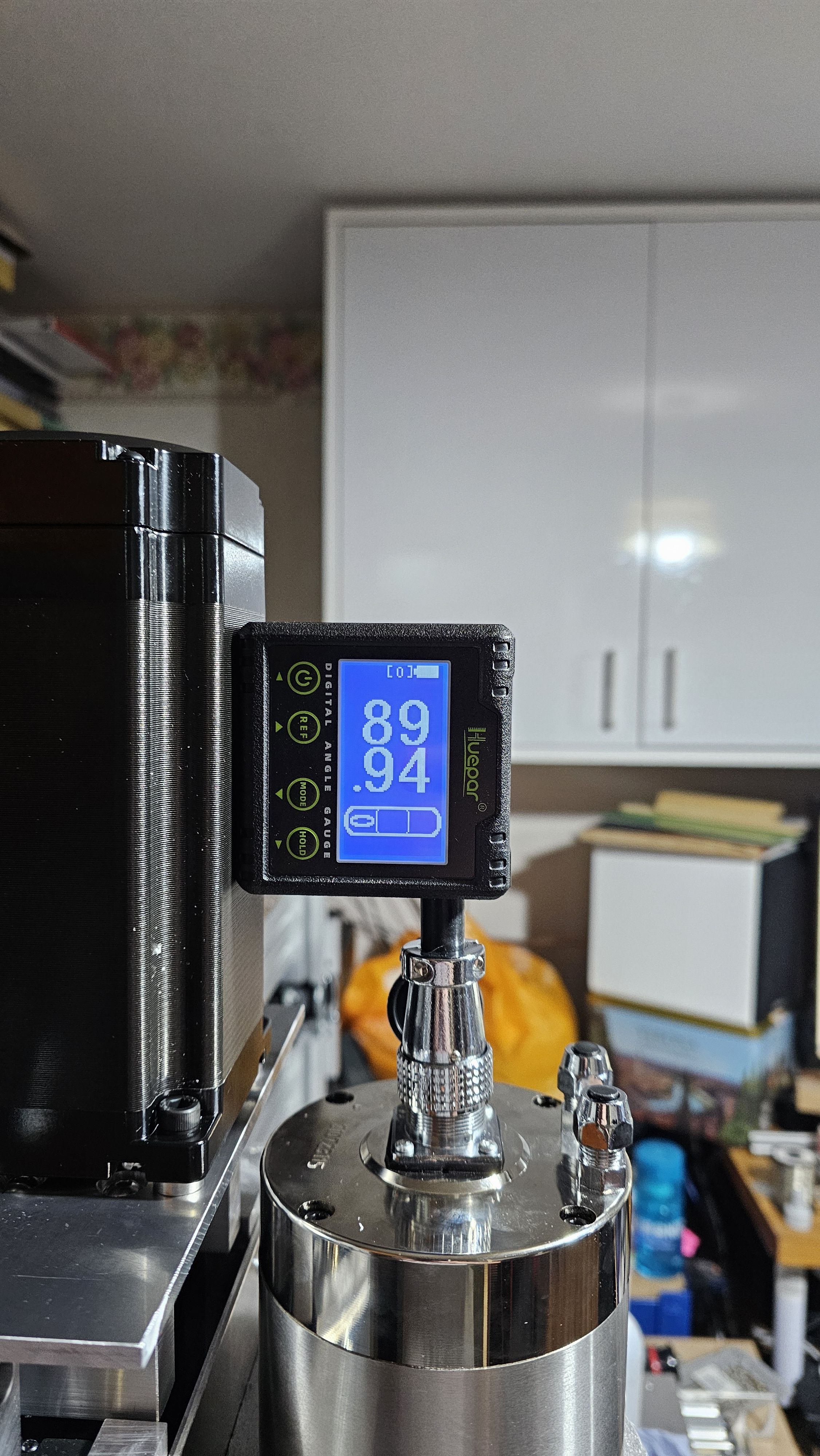
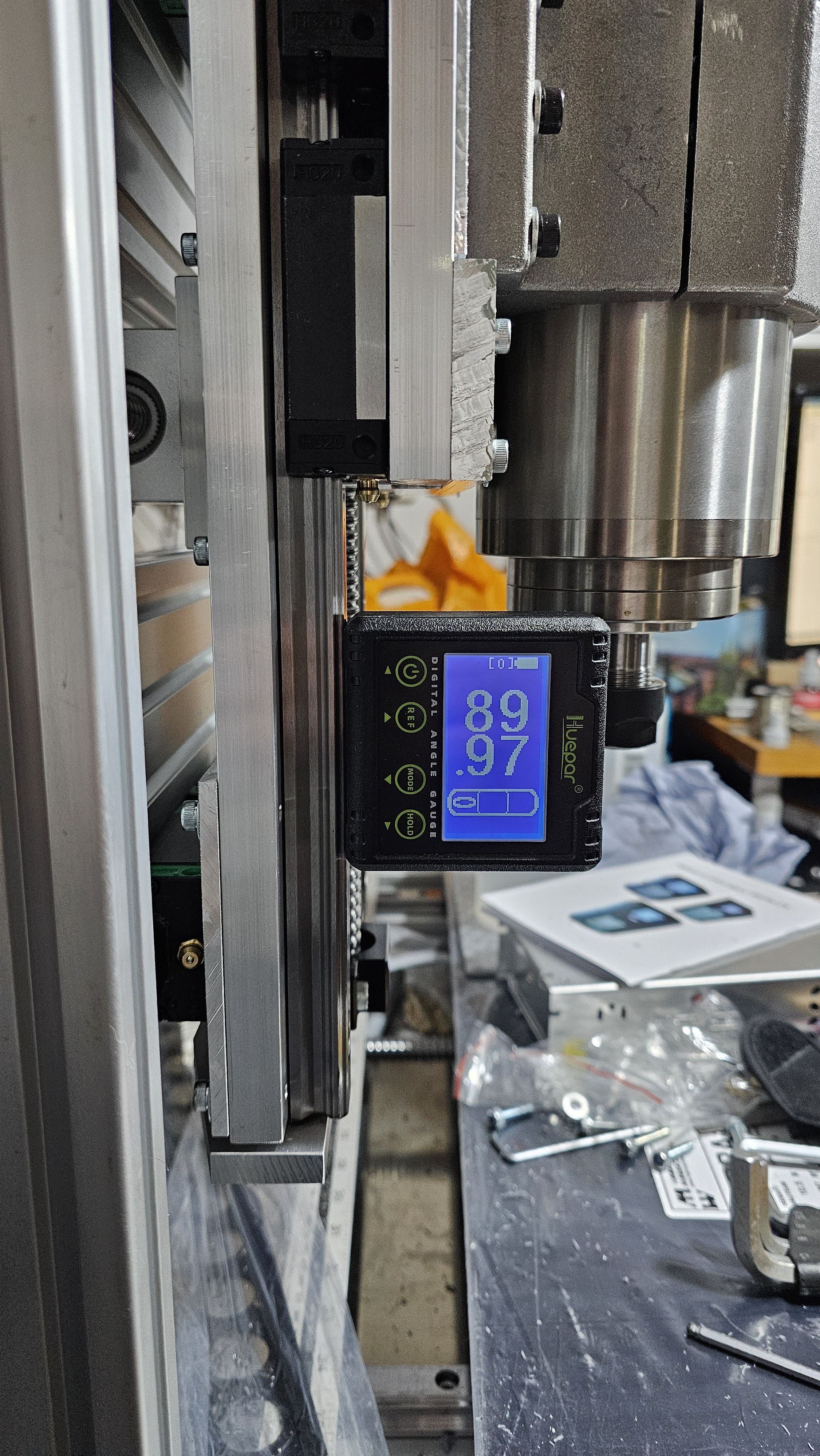
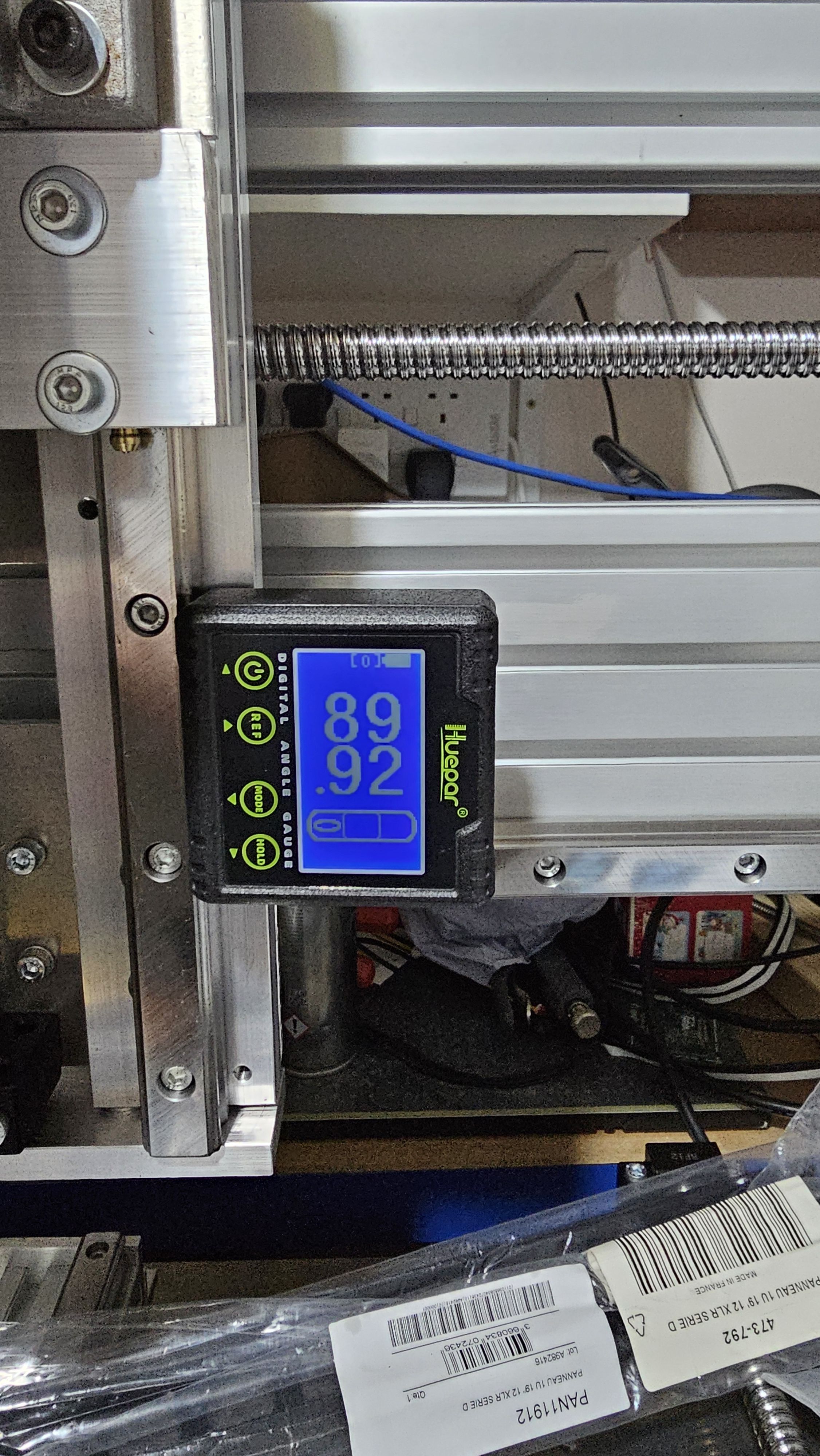
Overall, not too bad - especially as I hadn't really measured anything after cutting the bars, and had just let the CNC machine do the work.
The only one that would need to be addressed is the spindle, but 0.19° isn't bad (assuming the angle gauge is accurate!)
About the spindle accuracy
As I write this about 2 years after doing it, I realise that I've not really addressed this. This is because the 100mm spindle mount doesn't really have a lot of scope for adjustment. I have designed some new spindle mounts, but there's a couple of things that need to be sorted out before I can really machine them properly. Once I've done that, I'll be able to tram the machine - but it's accurate enough for the moment.
New bed
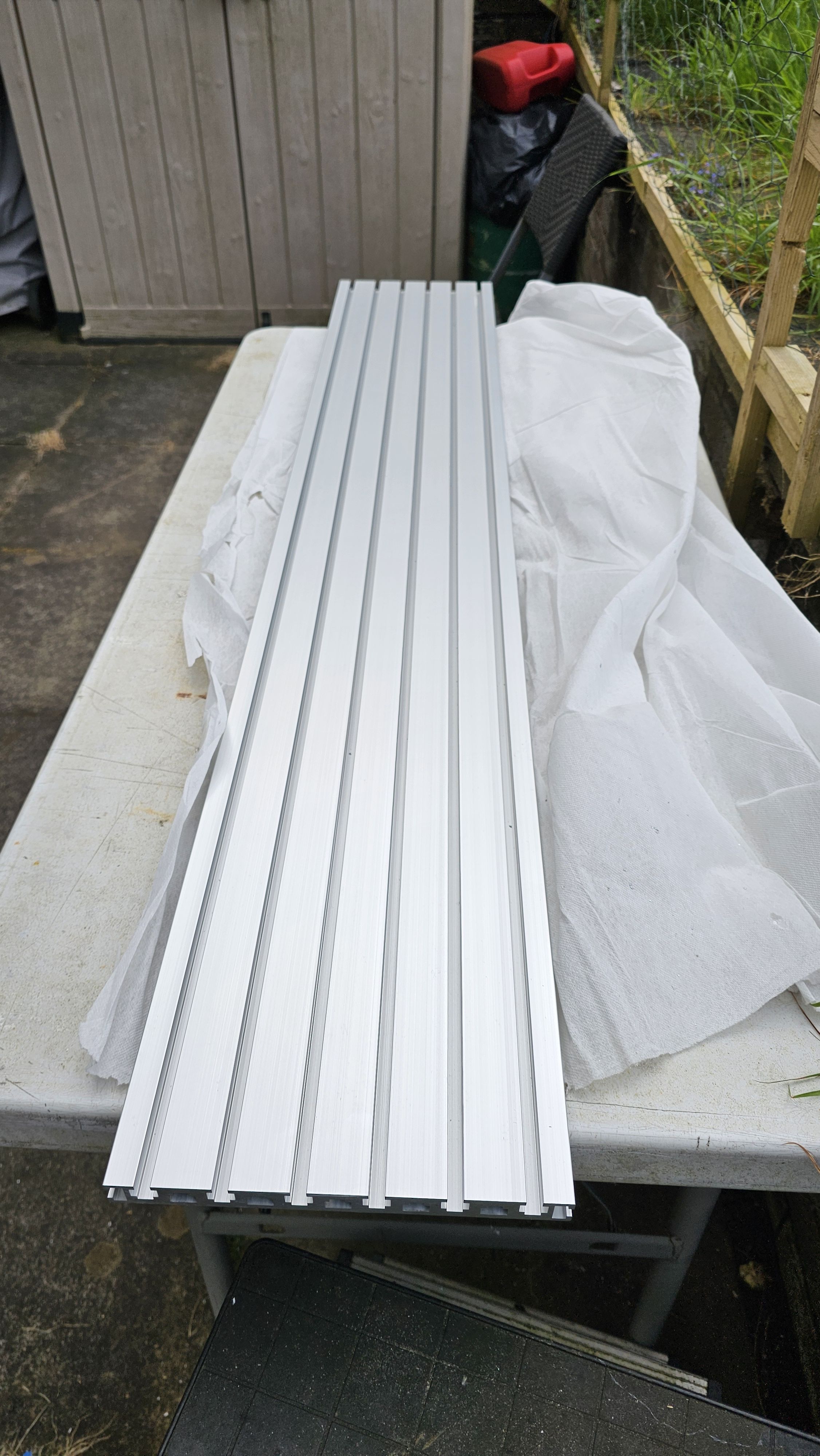
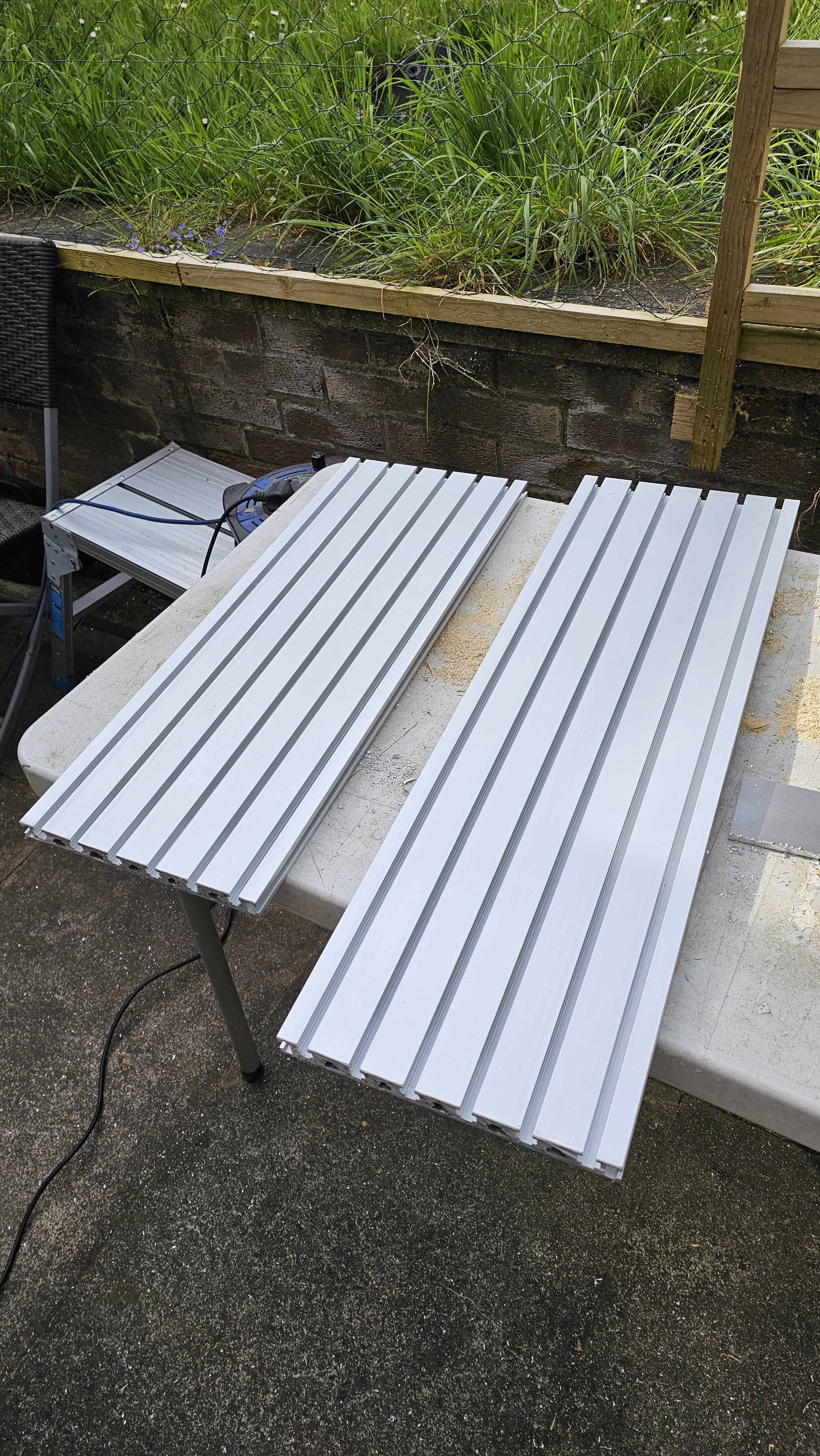
I found online something that could make a good new bed - it was quite a bit wider than my machine, but after cutting it, the spare bit could actually be used on CNC V4 (which I'll give to my brother, when I get the chance!)
Electronics front panel
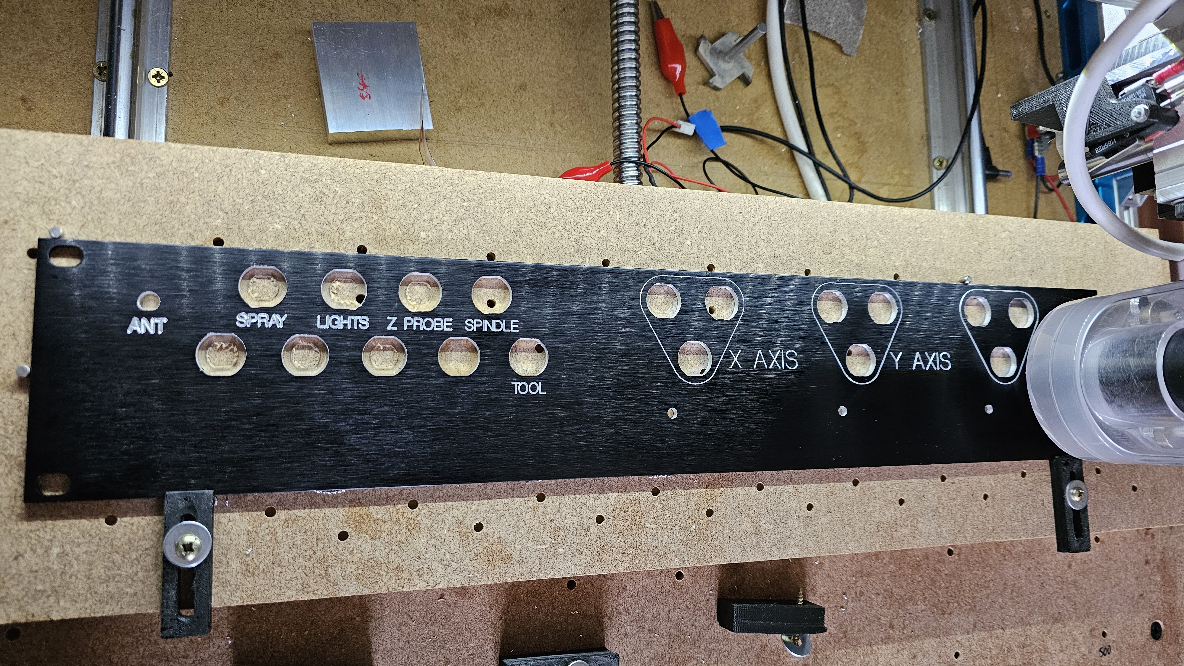
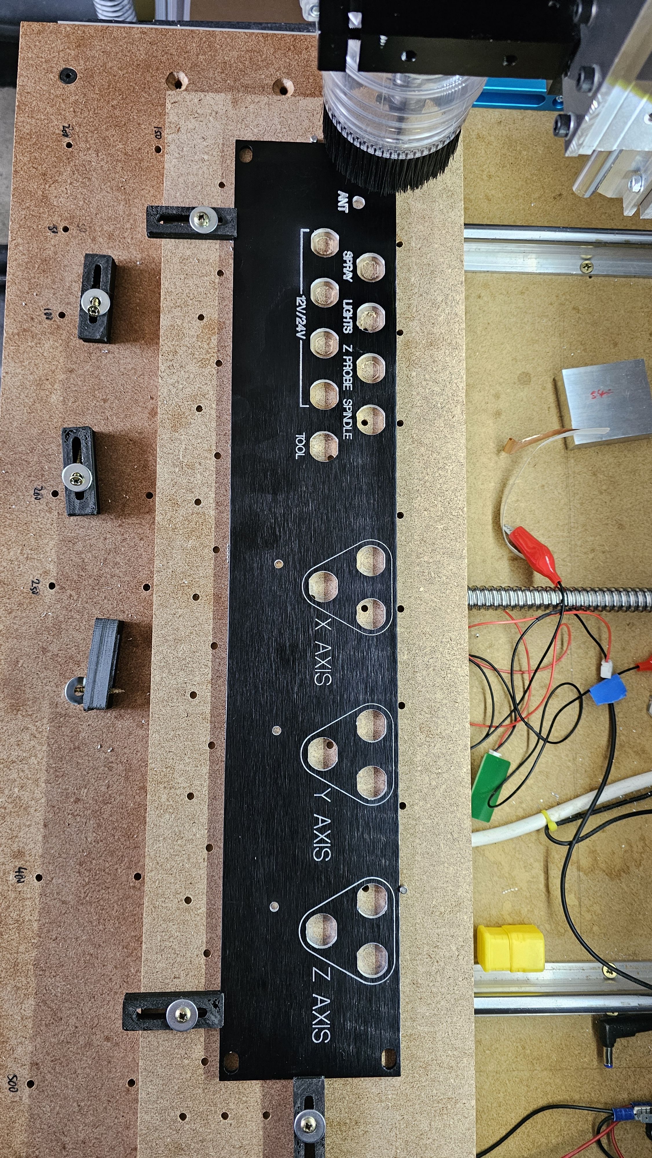
With the rest of the machine pretty much together, it was time to start on the electronics. Another thing that was going to be disposed of were a number of 2U panels. So I machined several of them, and got some GX "aircraft" connectors for them.
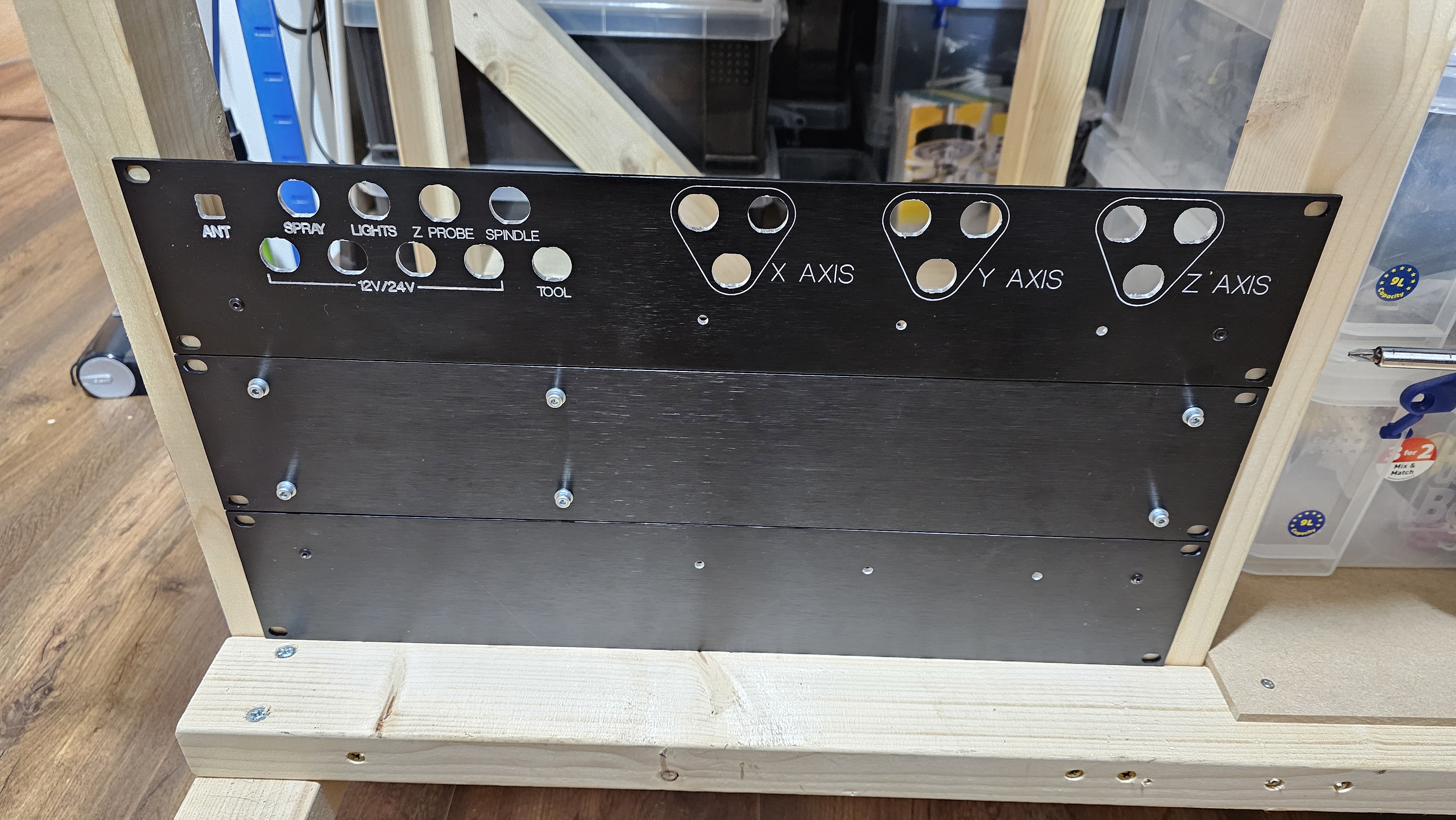
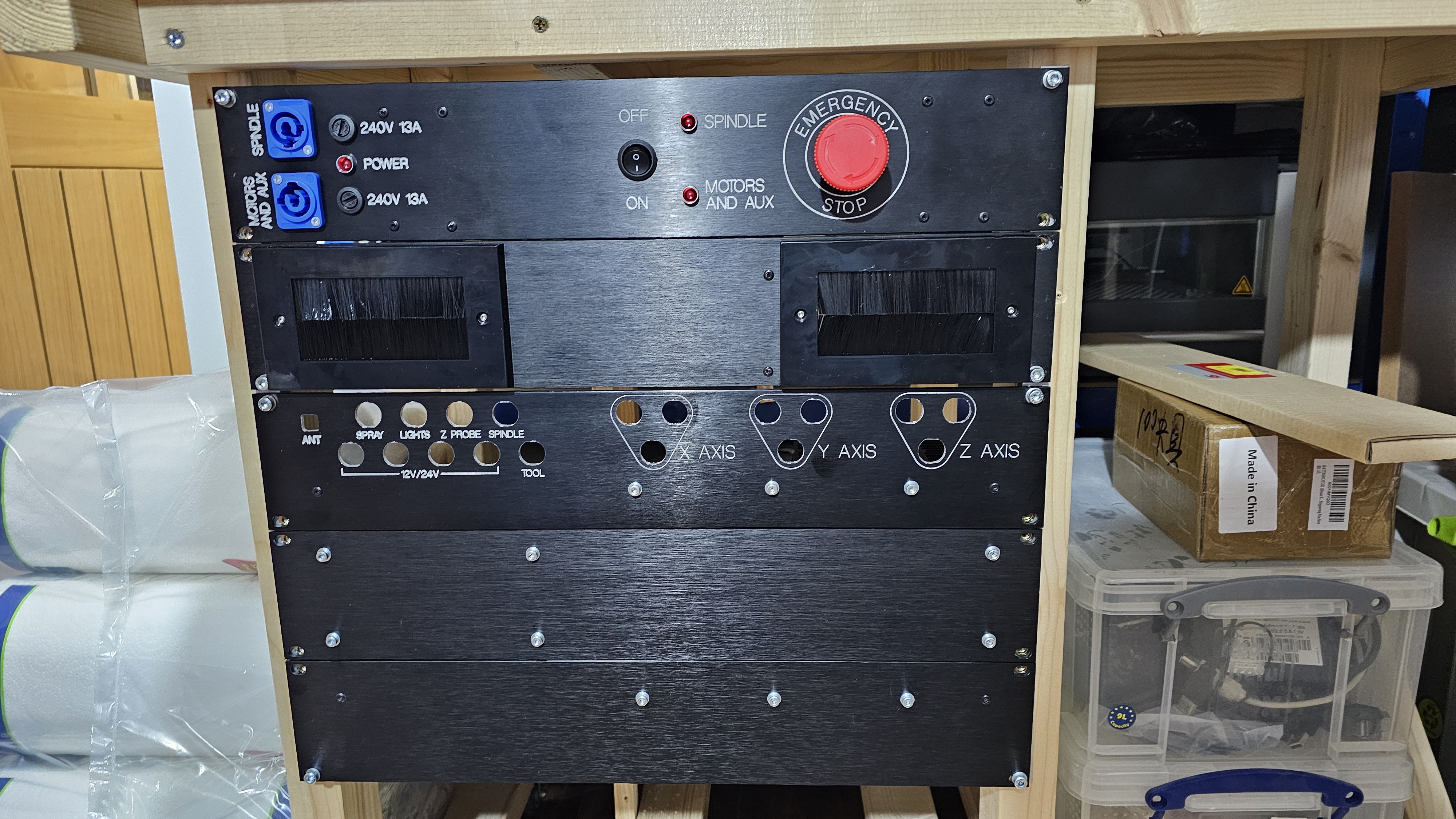
This is the main front panel, with connector positions for each of the axes and also auxiliary connectors (mainly 12V and 24V power):
Rough mounting on trolley
The panels would look something like this on the trolley:
VFD mounting
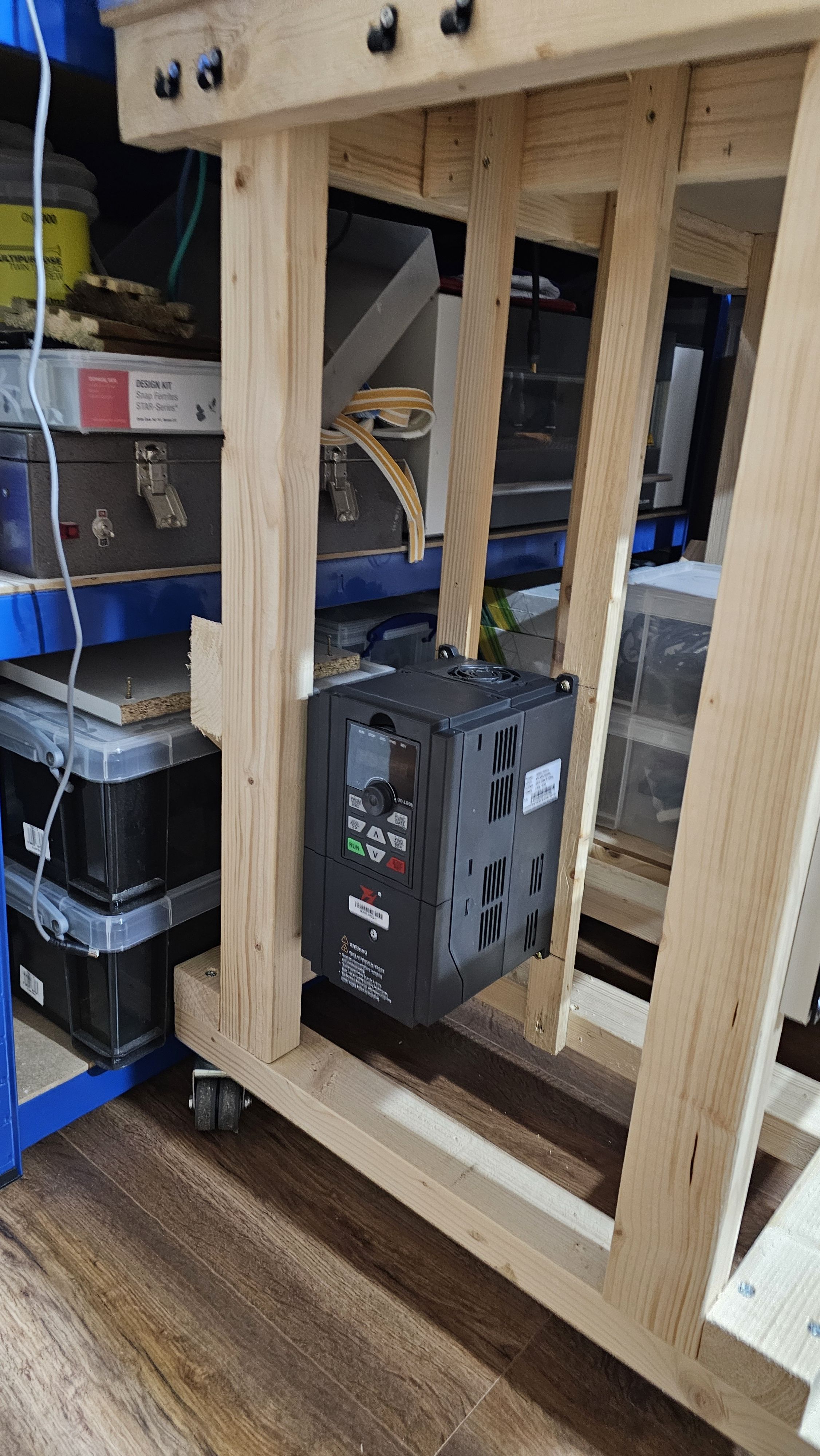
The VFD controller would need to be mounted at the back of the trolley
Panel mounting frame
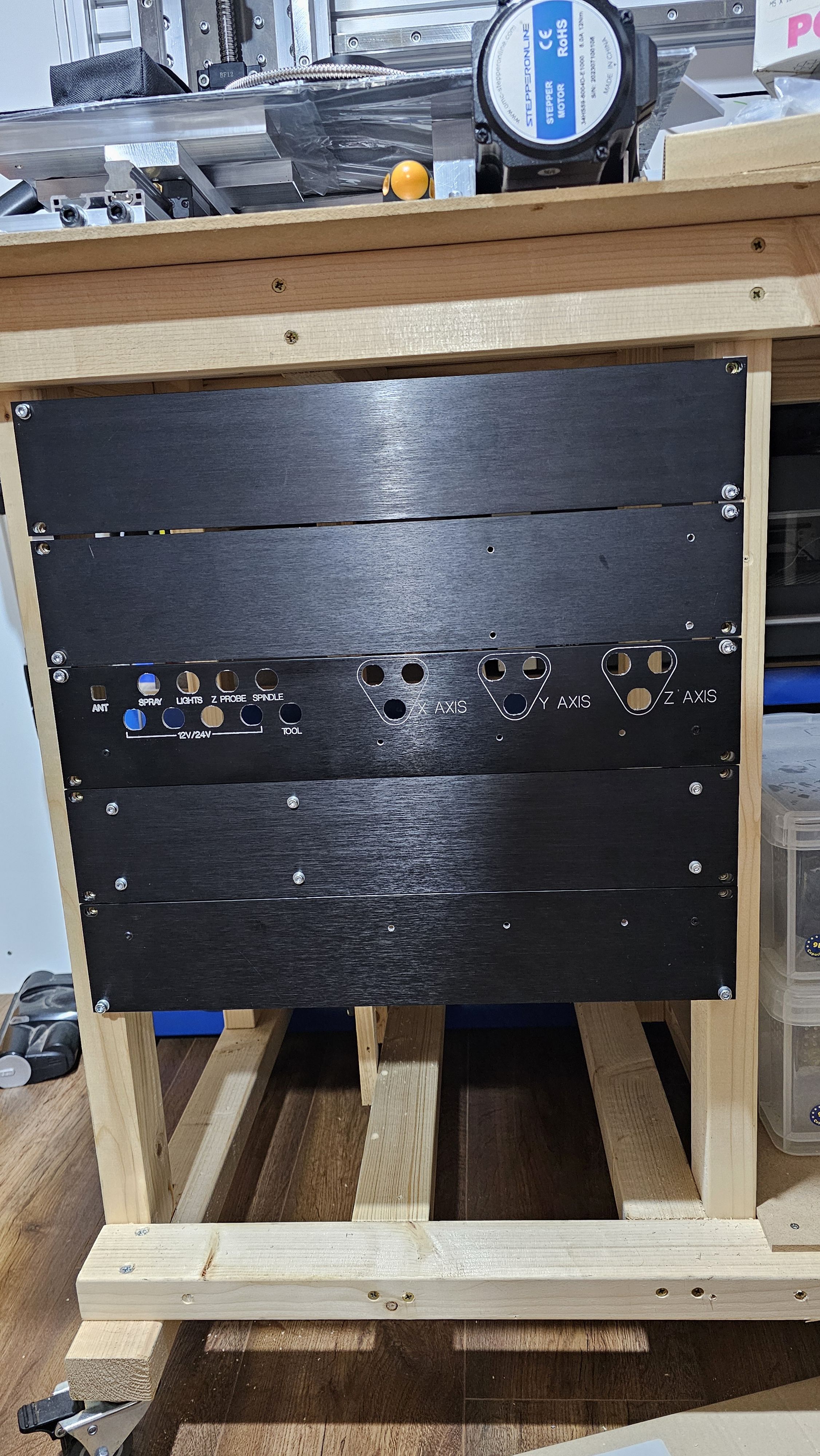
Using some U-shape aluminium from my local hardware store, I made some 19" rack frames to hold the panels. Rivnuts were riveted to the frame, allowing the panels to be mounted to the trolley:
Electronics mounting
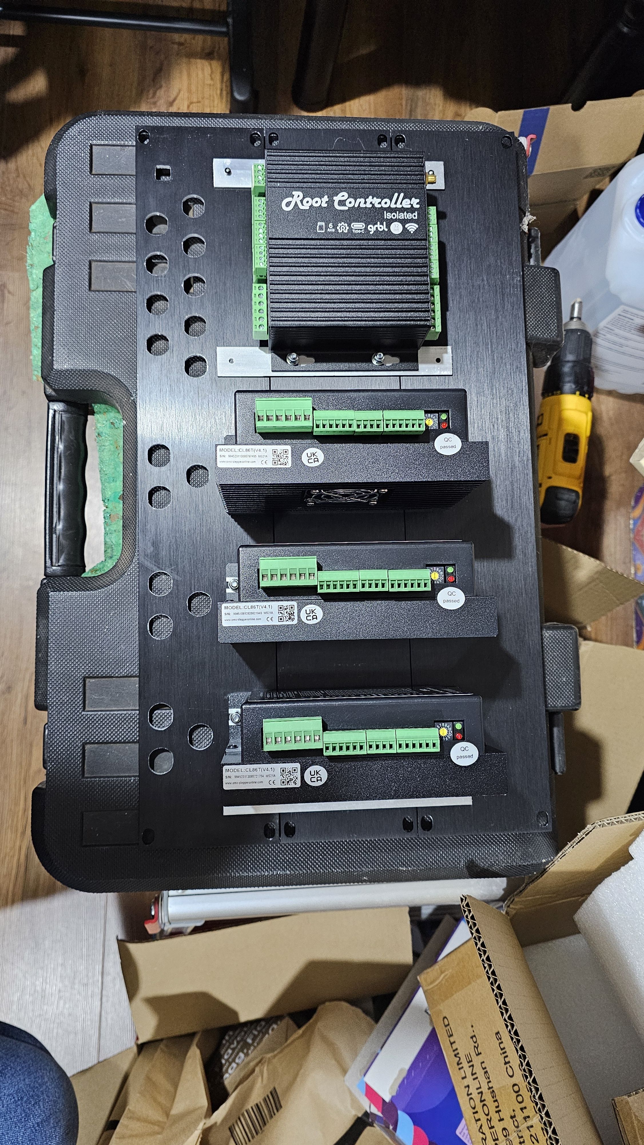
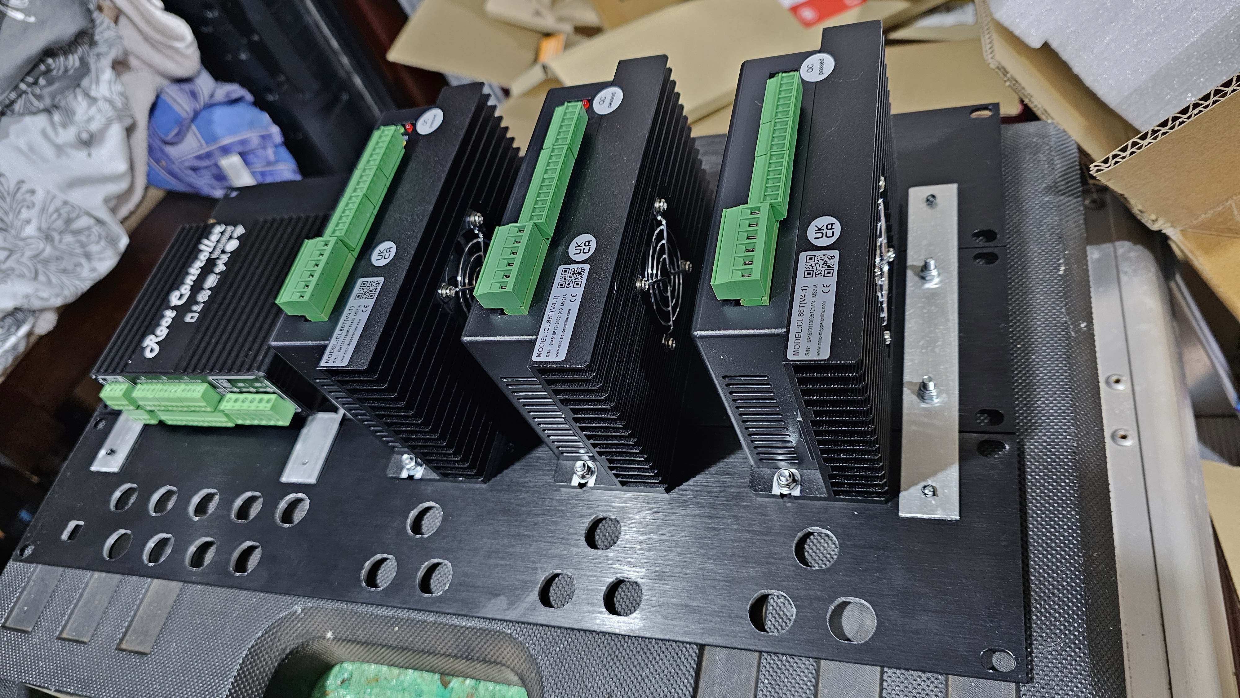
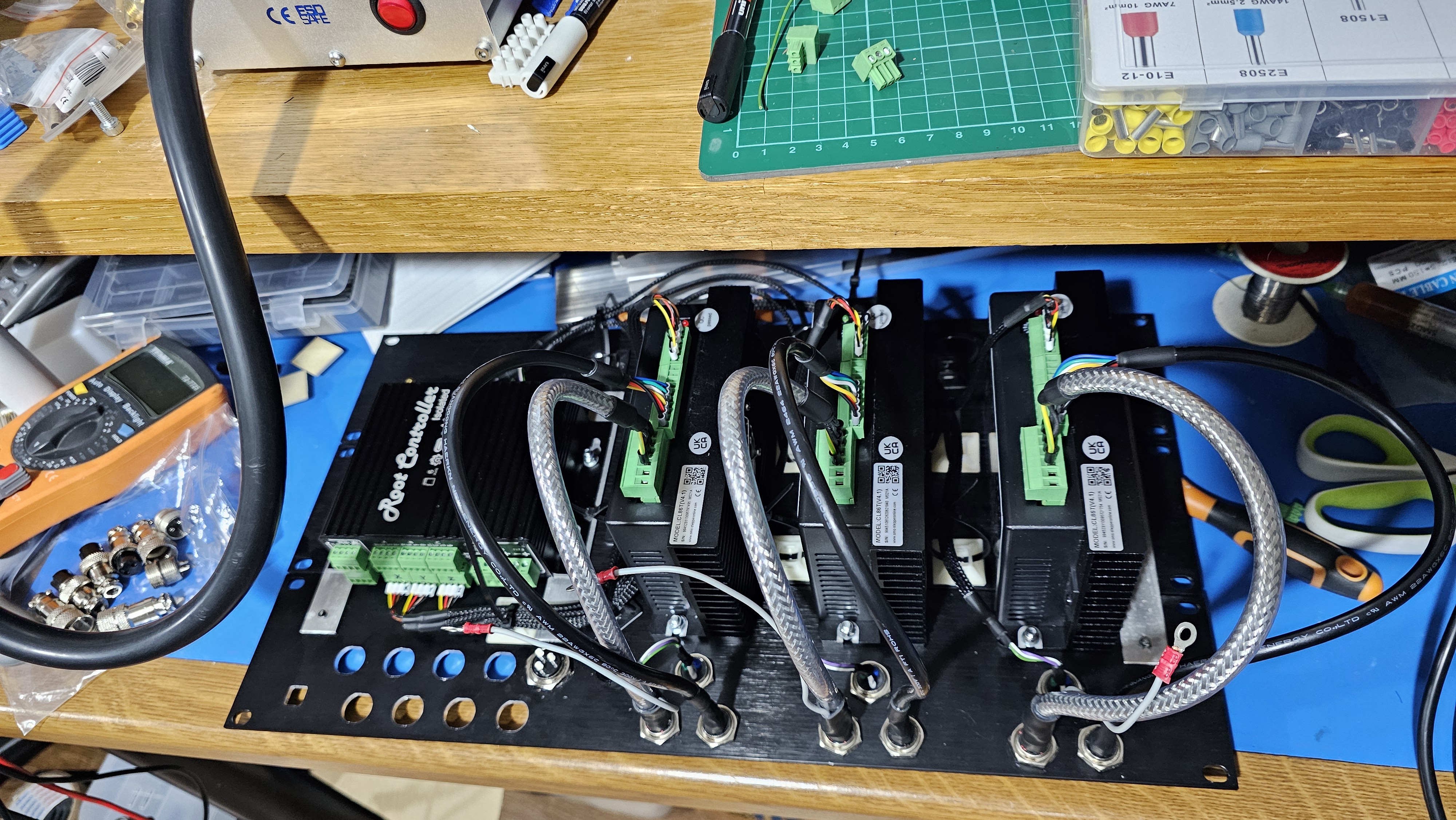
The stepper motor drivers and the Root Controller were fitted to three of the panels (along with some additional bracing to hold the three panels in place):
Power and emergency stop
Since the total power consumption could exceed a single UK power socket, I wanted two Neutrik PowerCon connectors at the front, and to help safety, an emergency stop switch. I happened to have a spare emergency stop relay (I wanted to experiment with it before introducing it to a design I was doing at work - although I ultimately used a better one).
I also needed all of the axes wiring to go through to the back of the machine - this is probably the biggest compromise of the design (I should've had these at the back, and not worry about the front).
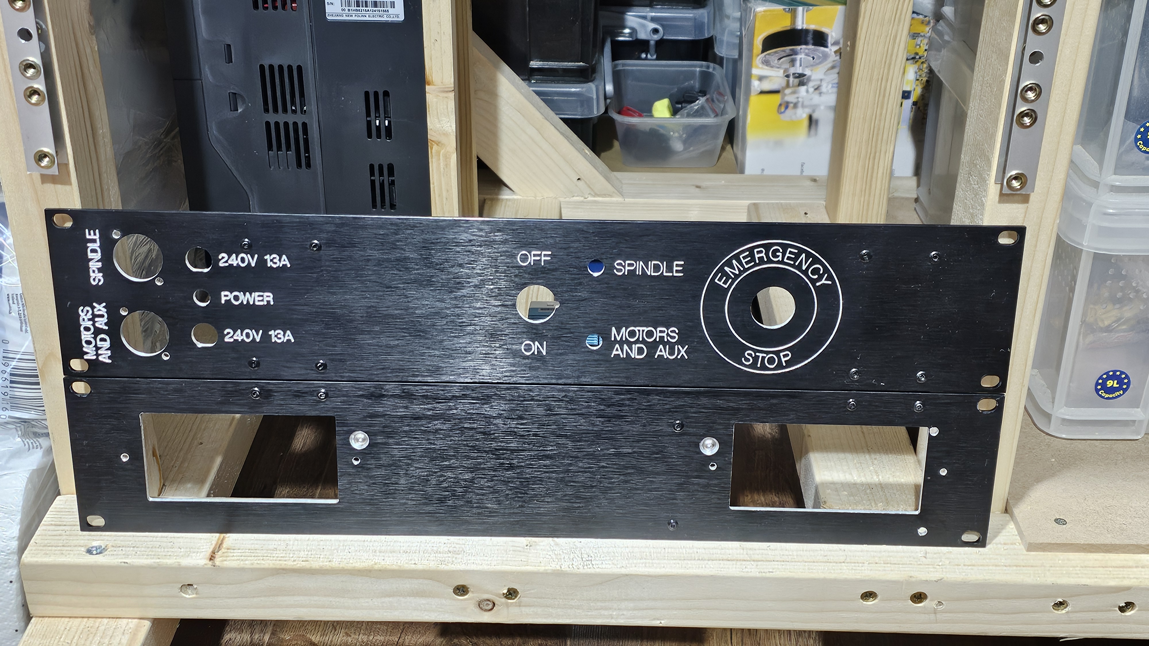
However, I did find some nice brush units that are designed for the UK plug socket size, and aimed at A/V systems. With all of the top panel connectors in place:
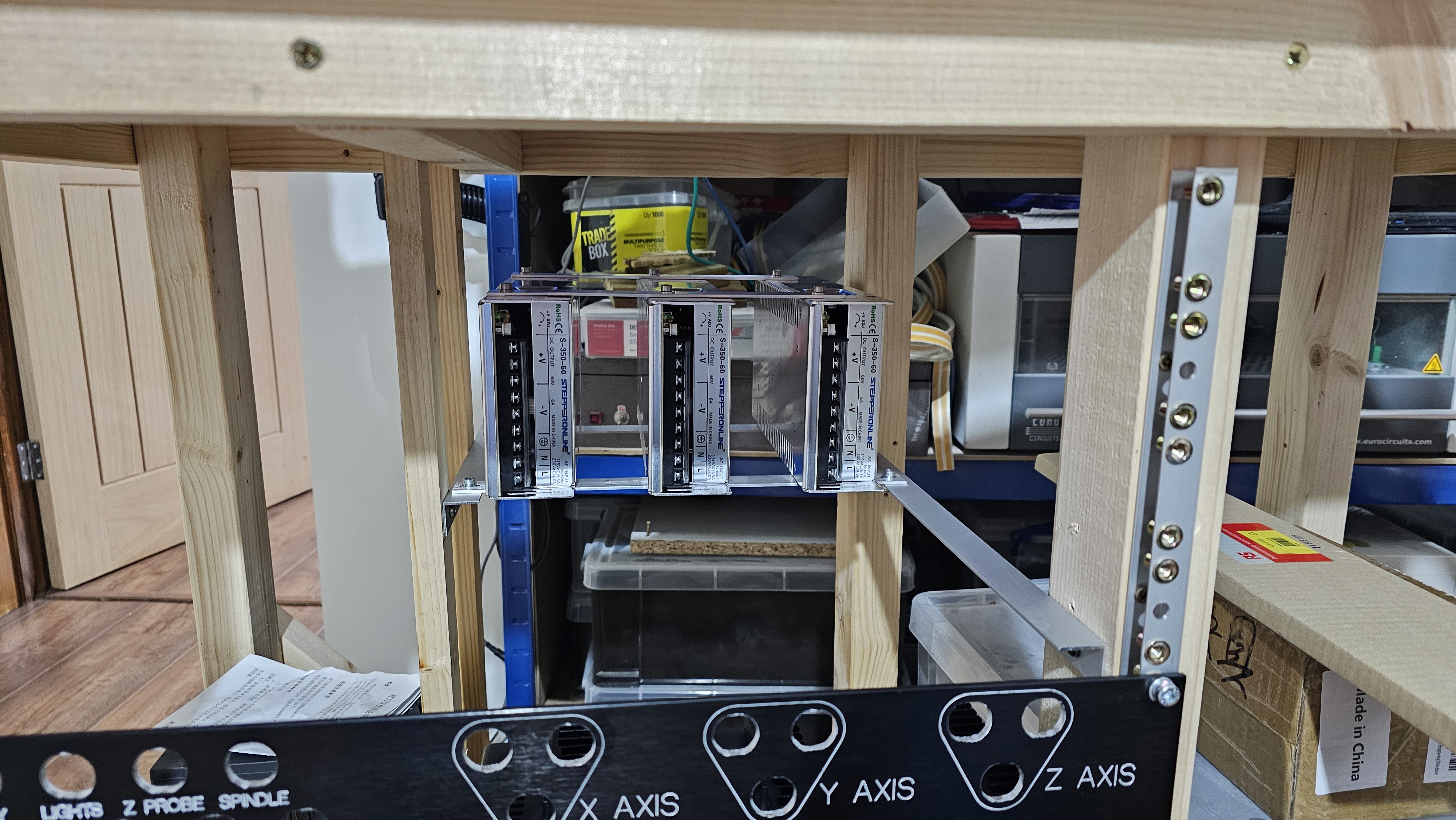
The stepper motor power supplies also needed a home - and this is at the top of the back of the trolley:
Electronics wiring
Each of the panel sets were wired individually, starting with the CNC controller and stepper motor drivers:
And then the emergency stop and power wiring
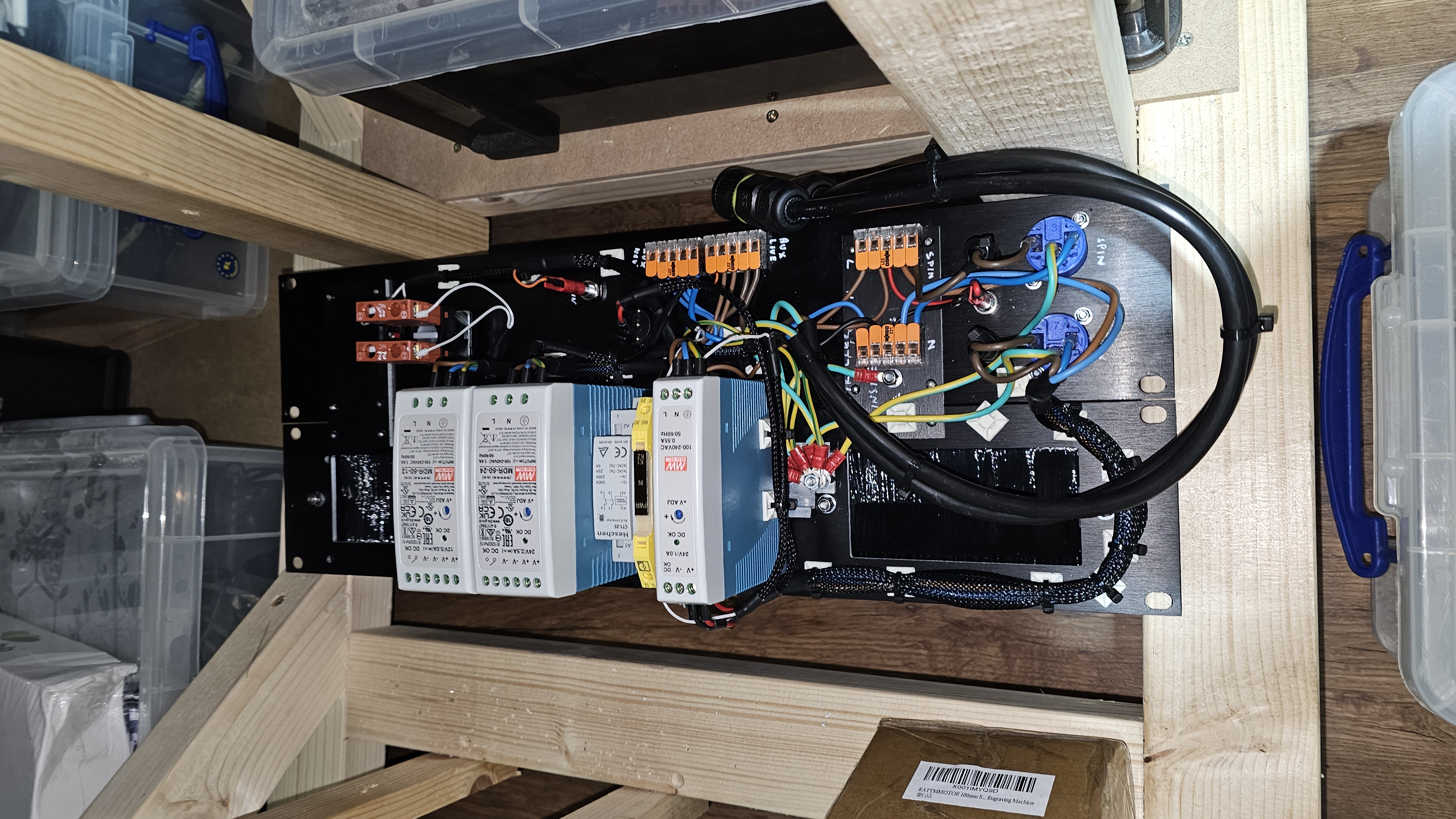
I'm quite pleased with the power wiring. It's split into two sections, with one of the power inputs providing power to the emergency stop mechanism and stepper motors, and the other to the spindle. The spindle's power supply also goes through a contactor connected to the emergency stop. If the emergency stop is pressed, then the spindle's power will be disconnected, and also the power to the controller will be cut, preventing any movement. This means that the emergency stop will cut everything off. In addition, if one of the supplies is not connected, then nothing will actually work.