- Elite
- Steel
Day 1 - Saturday 8th February 2003
The goals of this day were to get the first part of the frame assembled. The original plan was:
- Rectangle at base ("floor")
- Back
- Bottom wings
- Top bar
- Front triangle
- Remaining framework
I also did some modifications to the arrangement of the steel panels, and found that the model could now be 1.7m wide...
Getting everything together
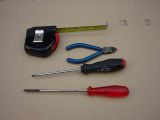
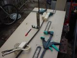
The first thing to do is to get all the tools ready.
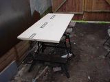
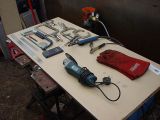
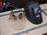
In order to get nice straight, flat edges, it is essential to have a flat surface in order to clamp material to while welding. Parts of the desk I'd made without this, and twists in the shape made it difficult to put the tops on. Note the welder is underneath the flat surface.
The left mask is the angle grinding mask, and the right mask is the welding mask. These are absolutely required for doing work of this kind.
Next stage
Now that the tools are ready, the next stage is very important.
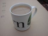
I'll enjoy this...
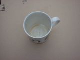
Ahh. That's better - now to continue.
Making the floor
The floor is a simple rectangle, 790x430mm in size. Two 790mm bars of the 25mm wide flat section were cut, along with two 380mm long bars (430mm - 2x25mm). I'm not worried about mitring the sections (it'll take too long), but I will dress the eges so that I can get a good weld.
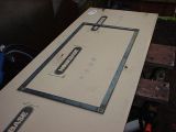
That's the floor done (although the picture doesn't show it with the welds cleaned up), now for the back.
Making the back
The back of the wings are 650mm long, and rasied at an angle of 10°. By marking 10° on the table, and holding the floor and the back of the wing at rightangles to the table, the back will be straight.
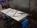
The other side is done in exactly the same way, and defines the wing span. Note that because it's only held at the weld, it's very flexible, so the rest of the back needs to be made. The remainder is made with the flat section parallel to the back, rather than perpendicular to it. This is because when the sheet is put on it, the flat really needs to follow the angle of the sheet. Since the back is the only angle we know at this moment, it's best to arrange the flat in that plane. The next section is 310mm long, at 40° to the previous angle. This was also made with the back laid against the table, and the floor perpendicular to it.
Before putting the top two bars on, a vertical was made, to make the height of the Cobra 330mm. The two lengths next to it were 930mm, and, like the previous section, were parallel to the back. Once these had put into place, the shape can be seen.
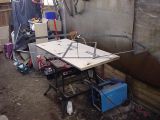
To give it some scale, here I am standing next to it
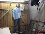
Making the top and front
The original plan was to make the bottom of the wings. That would be fine if the floor was perpendicular to the back, but it is not. The design for this was based on the Witchspace model, but as I indicated, there were things I didn't like about it, namely the angle of the back compared to the floor.
In order to 'fix' this (to my liking), the top was the next thing that had to be done - it would define the angles required for the wings.
I cut the top bar to the same size as the Witchspace model (430mm), with about an 85° cut at the end (instead of 90°) in order to angle the top downwards slightly. After welding it on, I decided that it wasn't long enough, and added another 50mm to it. This pushes the floor downwards at the nose, and brings the top of the back outwards, giving it the appearance of a straighter back.
All of the models had the nose as being roughly an equalateral triangle, so I decided that this would be the same.
The floor is 430mm wide, so I cut two 430mm bars, and a 30° angle at one end, welding them together so that they formed a 60° triangle. I then cut the bottoms off at 60°, and welded the top and bottom to form the basic shape of the body.
With it all cleaned up, it's looking good. It's also straight, which is really important to me.
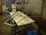
It was now dark, and raining, so I decided to call it a night there. Tomorrow's jobs are basically to get the frame finished, and possibly some of the mechanics prepared.
