- Elite
- Steel
Day 5 - Saturday 22nd February 2003
On the last day's events, I mentioned that I would be doing the feet today. Unfortunately, I didn't get a lot of work done today, because the company I work for needed some extra work doing. However, I was able to get one foot done (albeit with a lot of head scratching).
The first thing to do was to make the back of the body perpendicular to the floor by reducing the size of front leg. By raising the rear legs by 45mm, the back was vertical, which meant that the front leg needed to be dropped by 45mm. This meant around 80mm needed to be chopped from the leg:
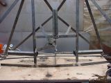
The design of the undercarriage meant that it 'poked' through the floor. Aesthetics require the floor to be smooth when the undercarriage is in the raised position.
In order to achieve this, the undercarriage floor section was split into two - one being the foot, and the other the back of the leg. Since the feet need to be flat with whatever surface it is on, they must pivot. The front foot is easy - the floor is only angled in the Z plane. The rear feet are harder - the floors are angled in the X and the Z plane.
With this in mind, I decided to start the rear legs. Using yet more of the frame material, I made a parallel section 82mm wide, ready to accomodate the 80mm wide flat bar I had from an earlier project, which was destined for the back of the leg and the foot:
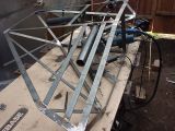
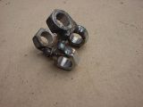
As the foot needed to pivot in the X and the Z planes, a form of universal joint was made (or rather the gimble from a universal joint), using a 25mm repair washer, and 4 M8 nuts drilled out:
An M8 bolt was welded to the top of one of the rear leg tubes, to extend it further. The gimble was attached to this, allowing the foot to pivot in the Z plane. Note that the Cobra is upside-down, so it looks like the bolt was welded to the bottom:
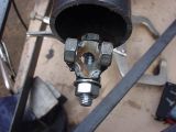
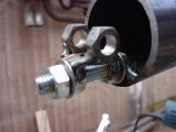
The foot was attached to the other part of the gimble using two small parts of frame material, and then the back of the leg was welded to the leg:
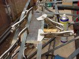
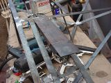
The horizontal bar at the bottom of the picture stops the foot from going in too far into the body, and also aligns it when it is closed.
Note that springs were attached between the leg and the foot to keep the foot in roughly the right position:
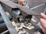
Finally, the model was turned the right way up, to see how the foot operated:
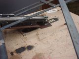
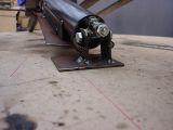
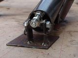
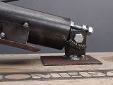
You can see how much the foot's angle is different to the back of the legs.
Anyway, that was it for today - tomorrow I'm driving 500 miles to get some RAM, so I probably won't get a chance to do any more until next weekend, when I want to get the other two feet sorted out, and then start work on the cockpit...
