- Elite
- Steel
Day 3 - Saturday 15th February 2003
Let me introduce you to a new tool:
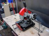
This is Mr. Chop Saw. It's like a woodworking mitre saw, except for steel. It has a TCT blade, with an oil bath, and a pump to pour oil over the blade while cutting. It is better than an angle grinder, because it cuts at an exact 90°. I bought it after making the desk, because one of the most difficult tasks was to make the desk's legs perpendicular to the floor.
Using the chop saw, two legs of 30cm were cut for the wings, and a third of 40cm:
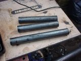
One problem with the chop saw is that it leaves oil on whatever it cuts. Trying to weld to oil is very difficult, to thinners were used to clean the legs of oil:
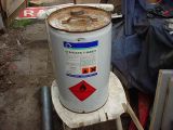
This is flammable stuff, and must be kept away from any welding and angle grinding - I've been involved in 3 minor fires that have been fueled by thinners, and seen the after effects of a major fire.
I get my thinners trade - which means this tub is around £12. You can get a 500ml bottle of thinners from a DIY shop for £7, so this is very good value.
Not only are thinners flammable, they are also not very nice to work with. I've used them a lot, so I'm used to it, but when I first used them, it was quite uncomfortable.
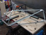
After cleaning them, I put them roughly where they'll be:
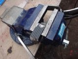
The next stage was to mount the legs on the frame. Six tags were cut from the same material as the frame. They were then clamped in a vice, trimmed identically, and then drilled with an 8mm hole:
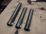
Holes were drilled into the tube, 3cm from the top, and an M8x70 bolt threaded through to tags to each tube (along with washers and a nut):
Using some more frame material, a cross-member was welded into place between the floor frame sections. Then, after carefully marking the centre line, and the required positions of the tags, the tags were first spot welded on, and then fully welded into place:
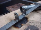
The other two legs' tags were welded in a similar fashion:
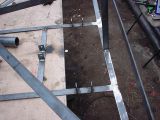
The legs were then bolted back in just to see what it looked like:
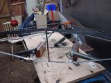
Since the nose of the Cobra points up, the bottom of the cross-member was sectioned (bits cut out) to allow the front leg to go down further. In addition, strengthening rods were inserted between the cross-member, and the top of the frame
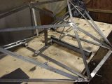
The next stage was to make the legs move in unison, by connecting them together.
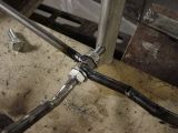
Lengths of 8mm rod were cut, and nine 8mm nuts were drilled with an 8mm drill bit (lots of 8mm bits going on here!). The nuts were then inserted over the rod, and then welded on to the top of each tube. These formed sliding rods that can be used to connect all three legs together.
Since the rear legs need to follow the angle of the wings, the front leg's rod was bent to allow the rear legs to be positioned at a higher angle.
The end of the front leg's rod was then threaded to allow nuts to hold two other drilled nuts welded on to the end of the rear rods.
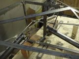
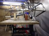
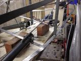
And with the legs up...
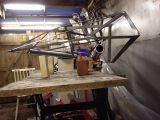
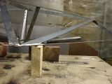
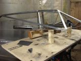
A closeup of the join:
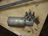
Tomorrow's job is to get the motor fitted. Here's a picture of it (after it was stripped from the wiper mechanism):
