- Eagle PCB
- Electronics
- Xilinx
The board
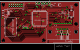
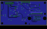
The PCB layout is as follows:
Top

Bottom

Design
This is exactly the same width as the XilMezzie board, but is a bit longer to accomodate the VGA connector and SRAM chip.
I've put all the signal smoothing capacitors on the bottom of the board (except for the Tantalum ones, and the one for the configuration device). Also, the JTAG interface now uses through-hole pins instead of SMT (this change has already been back-ported to the XilMezzie boards [both 3E and 3A]).
The only other change is that I've used an 0603 LED instead of 1206.
I'm not terribly happy about running two of the red signal wires through the crystal - however, I didn't have a lot of space to do it any other way. I'll see if I get cross-talk there (I've tried to shield the crystal output from those pins as much as possible).
