- Electronics
- Microchip PIC
- PicoBlaze
- Source code
- Xilinx
Optimisations
In preparation for the write, I had a look at the timing - the read operation was taking twice as long as it needed to (it was reading in 50MHz, whereas it should be able to read at 100MHz). This would give me much more write bandwidth.
So, I did a bit of playing with the system, generating a video and a memory clock. Unfortunately, due to an unknown timing issue, I found that the memory clock had to be under 80MHz, and also the video clock an integer multiple of the memory clock.
As a result, the main clock is now 150MHz, with the memory reads taking two clock cycles (75MHz), and the video using three clock cycles (50MHz).
Connecting card
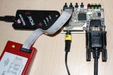
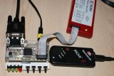
I was initially powering it from the Spartan 3E development kit - but I wanted it to have a separate power board, with a processor on it. For testing, I went for a PIC18F4620 (it's a very well featured chip, and runs at a resonable speed). For my car dashboard, it'll be replaced by an ARM.
This is a simple board with the PIC, and a 3.3V power supply on it. I also put some switches and status LEDs on it, in case I need something other than the display to tell me something's going on.
Using the real display
Instead of using my main 24" monitor, I got the monitor I wanted to use (or rather the type of monitor I was aiming at) - a 10" automotive display running at 800x600. I plugged in the VGA cable, and turned it on.
Out of range was the message that appeared. Damn - the 50MHz speed was too fast. A quick reprogramming of the chip to use a 40MHz video clock (and 80MHz memory clock - faster, yay!) made it work, albeit at a lower refresh rate (it should be 72Hz):
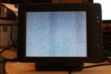
This display also has a slight blurry bit - this can be changed by adjusting the 'clock' setting, but this is what the automatic setting decided.
Communications
I've got an SPI bus to connect to a microcontroller (the FPGA will be a slave), but that would slow down the communication to the display. As a result, I decided that I needed a two-tier system, with an embedded processor on the FPGA to take the SPI commands and interpret them for display.
After a long think about it, and a bit of research, I went for the Xilinx PicoBlaze processor - this wouldn't allow me to implement a full display, but it would be able to do some simple things. What I'd like to do is for it to perform the following commands:
- Set current colour
- Fill rectangle
- Outline rectangle
- Draw bit pattern
- Draw byte sequence
- Plot pixel (although that could be a small rectangle)
- Draw horizontal and vertical line
If there's enough instructions left (only 1K is available), then maybe an arbitrary draw line instruction too.
Writing to the display
To test the PicoBlaze integration, I wrote some very simple code to just repeatedly write to the screen with an incrementing colour (which increments each frame filled).
This code looks like this:
addr0           EQU     sC
addr1           EQU     sD
addr2           EQU     sE
colour          EQU     sF

lowaddr         DSOUT   $01
midaddr         DSOUT   $02
highaddr        DSOUT   $04
ocolour         DSOUT   $08

begin:
                DINT
                LOAD    colour, $00
outerloop:
                LOAD    addr0, $00
                LOAD    addr1, $00
                LOAD    addr2, $00
loop:
                OUT     addr0, lowaddr
                OUT     addr1, midaddr
                OUT     addr2, highaddr
                OUT     colour, ocolour

                ADD     addr0, $01
                ADDC    addr1, $00
                ADDC    addr2, $00

                COMP    addr1, $53
                JUMP    NZ, loop
                COMP    addr2, $07
                JUMP    NZ, loop

                ADD     colour, $01
                JUMP    outerloop
I've used individual bits for the output port ID to signify the address it's writing to, and also the colour data. This very much simplifies the internal wiring.
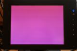
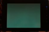
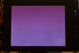
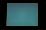
I then did a fair amount of simulation to iron out little problems to do with the write buffer (I didn't have a way to test it), and then gave it a whirl. I was very pleased and surprised to see the screen change colour in the way that I had expected:


Current FPGA utilisation
In order to see if I can use an XC3S50A-144 for the 16-bit version, I'm keeping an eye on the utilisation figures. They currently stand at:
- Occupied slices: 382
- DCMs: 2
- RAMB16BWEs: 4
The XC3S50A has:
- Slices: 704
- DCMs: 2
- RAMB16BWEs: 3
The last one is a bit concerning - I could change the SPI FIFO to a slice-based FIFO, but that would end up using more slices. Luckily the FIFO doesn't need to be that big, since I've done a bit of cleverness that allows the controlling CPU to determine if it's full without issuing a write sequence (it's a zero-bit write).
