- Electronics
- Xilinx
Initial tests
The day after soldering it and making sure it was electrically okay (i.e. no accidental short between ground and power, and between other pins), I programmed the FPGA to give a test signal based on the code in the book FPGA Prototyping by Verilog Examples, modified to:
- Suit my programming style
- Use 9bpp RGB
- Generate the right signal for 800x600 (instead of 640x480)
When I'd done this, I programmed it straight to the FPGA rather than simulating it - it's not a terribly complicated thing to do.
Unfortunately, it didn't work - so after doing a bit of verification, I decided I needed to simulate it.
What I hadn't realised is that the HSYNC and VSYNC signals were inverted to what they were supposed to be - I didn't have the schematic for the dev kit used in the book, and I'm guessing it goes through a transistor so you need to invert the signal.
So, with that fixed, and it simulating correctly, I had another program of the FPGA.
Still zilcho.
So it was out with the oscilloscope and make sure the FPGA was generating the signals. Yup - HSYNC and VSYNC were being nicely created. However, when I put the 'scope on the VGA connector, the signals were very weak - too weak.
Since I'd based that part on the Spartan 3E dev kit, I had a check of the resistors being used (I though that 82.5K was a little high when the others were 240 ohms). Arghhh - they should've been 82.5 ohms (only 1000 times smaller than I'd bought).
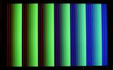
Unfortunately, I don't have any 82.5 ohm resistors available - but I do have some 100 ohm resistors. They'd have to do (it's difficult to get resistors the right value at 11pm on a Sunday!). It then worked - and gave this test signal:

The colour bands are based on the horizontal pixel value - unfortunately, there isn't enough to get as far as 7,7,7 RGB value (well, not without stepping a bit).
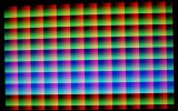
So, I chose a different pattern - during which I also added in code to make the RGB values 0 when it's doing front/back porch or flyback signals (the monitor I'm using didn't like it very much if I didn't).
The new test signal looks like this:

Next, I'll interface the RAM and see what I can do with it...
The plan is to read the RAM in 10ns, and use the other 10ns to write to the RAM based on a write buffer that will contain the address and data to read. The data will be 8-bit, and the address 18-bit, which means I can use a block RAM for the write buffer (a simple FIFO).
Another block RAM will be used for the palette, and I may even add in a hardware cursor at some point...
