- Electronics
- Microchip PIC
- Xilinx
Instruction set
I've done a bit of preparation before writing the PIC code - the PIC will need to do some of the work for the PicoBlaze processor, such as converting coordinates to addresses.
The instruction set is currently as follows:
- 0x00 - Null instruction (NOP)
- 0x10, {col} - Set colour to {col}
- 0x11, {low}, {mid}, {high} - Set address to 0x{high}{mid}{low}
- 0x12, {skip} - Add {skip} to address (0x00 means 256)
- 0x13, {sk1}, {sk2} - Add 0x{sk2}{sk1} to address
- 0x20 - Draw single pixel at current address
- 0x21, {len} - Draw {len} pixels (0x00 means 256)
- 0x22, {l1}, {l2}, {l3} - Draw 0x{l3}{l2}{l1} pixels
- 0x30, {len}, {bits1}, {bits2}, ... - Draw {len} byte pixel images (bitfield, using current colour)
- 0x31, {len}, {pix1}, {pix2}, ... - Draw {len} pixels
All other commands are NOPs.
Trying a route on X3C50A
When I'd done bits of the code, I did a trial fit on an X3C50A. Initially, it didn't want to map because I'd used too many RAMB16BWEs (even though I'd translated the SPI buffer to distributed RAM, rather than block RAM). I found out that my write buffer was too large to fit into one BRAM, so I made it half the size (that'll teach me not to read the summary page!). I think that happened when I changed it to a fall-through FIFO (which meant it needed 1025 memory addresses instead of 1024).
However, even with that solved, it couldn't then place and route - it ended up with 928 signals left to route. So it looks like I'll need to go to the X3C250E for the 16-bit version.
But having said that, I could make my own CPU for the graphics - there's a lot of the picoblaze that I'm not using, such as the scratchpad RAM, and about 11 of the 16 registers (although that may change as I implement the commands).
Another option I've got is to put multiple CPUs into the chip, and parallelise the SPI instructions. That would be neat.
Getting the PIC to communicate with it
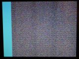
I knocked up a quick SPI writer using the PIC, with the additional zero-bit read to make sure the FPGA wasn't busy. It didn't draw anything, but I realised later on it was because the monitor hadn't synced to the signal properly, and wasn't displaying the first line. So, I made it draw a band using colour 0xf0 (which should be B:111, G:110, B:000 - i.e. a blue-cyan colour). Lo, and behold, this came out:

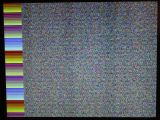
I then used the line number to select the colour:

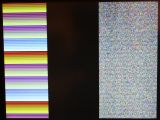
All of these were 128 pixels wide - I found that if was more than that, then it became unstable due to the FIFO filling up. As a result, I adjusted the zero-bit code so it de-asserted the SPI enable line. This would mean that the SPI output buffer would be reset with the SPI FIFO full flag. I also slowed the PIC from 32MHz to 8MHz. This made it a bit more stable - and drew 255 pixels, followed by a black 255 pixel wide band:

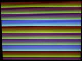
I missed the fact that the black line wasn't straight. I'm not sure why it's done that; I only noticed it when I was cropping the picture - if I had noticed it, I would've done some more tests. Instead, I drew the whole horizontal line, and also got the moitor to auto-adjust to the signal:

And then I called it a night. I'll try drawing something a bit more interesting soon.
