STLCutter 2 - Day 2
Today's aim was to finish off the Z-axis mechanism.
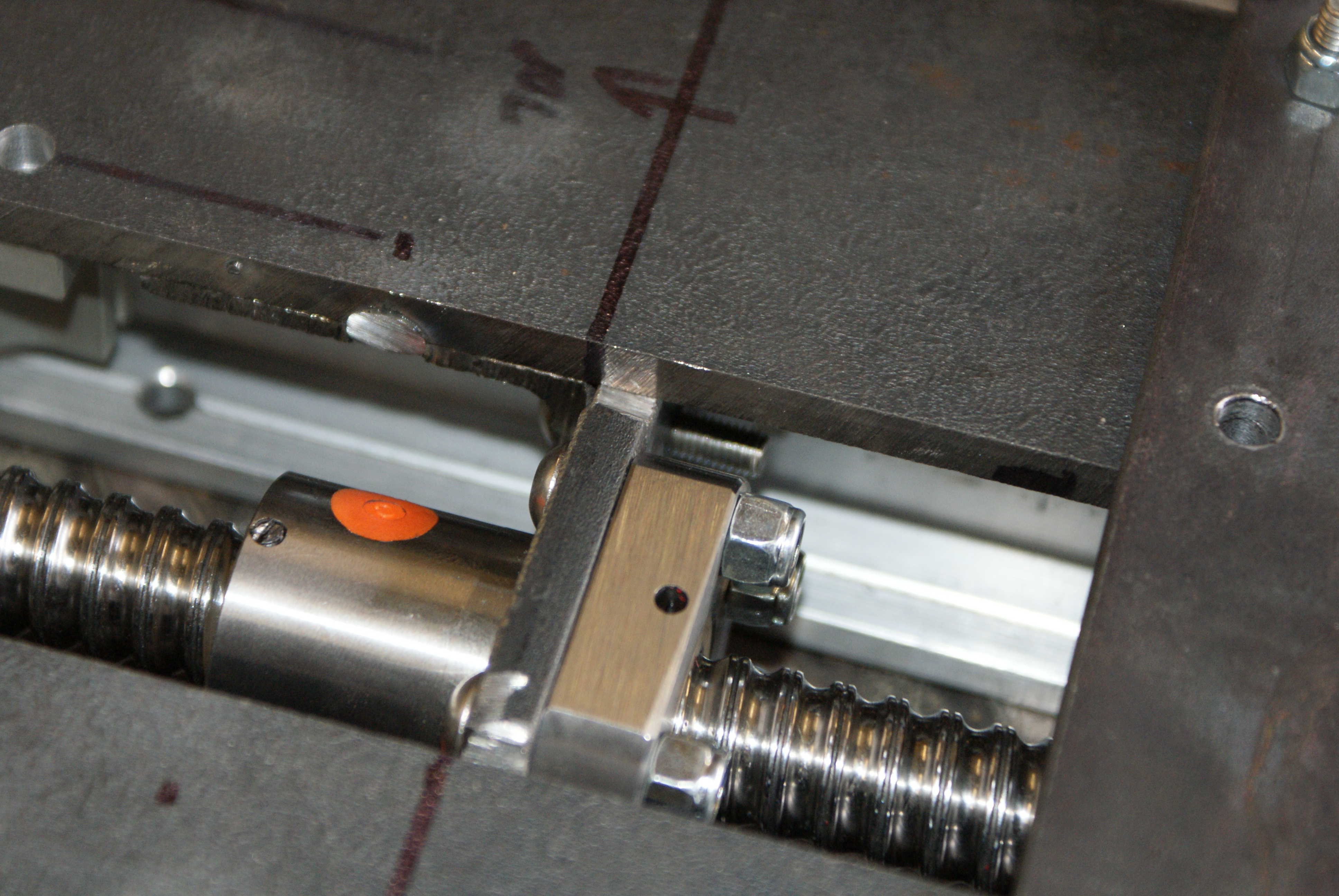
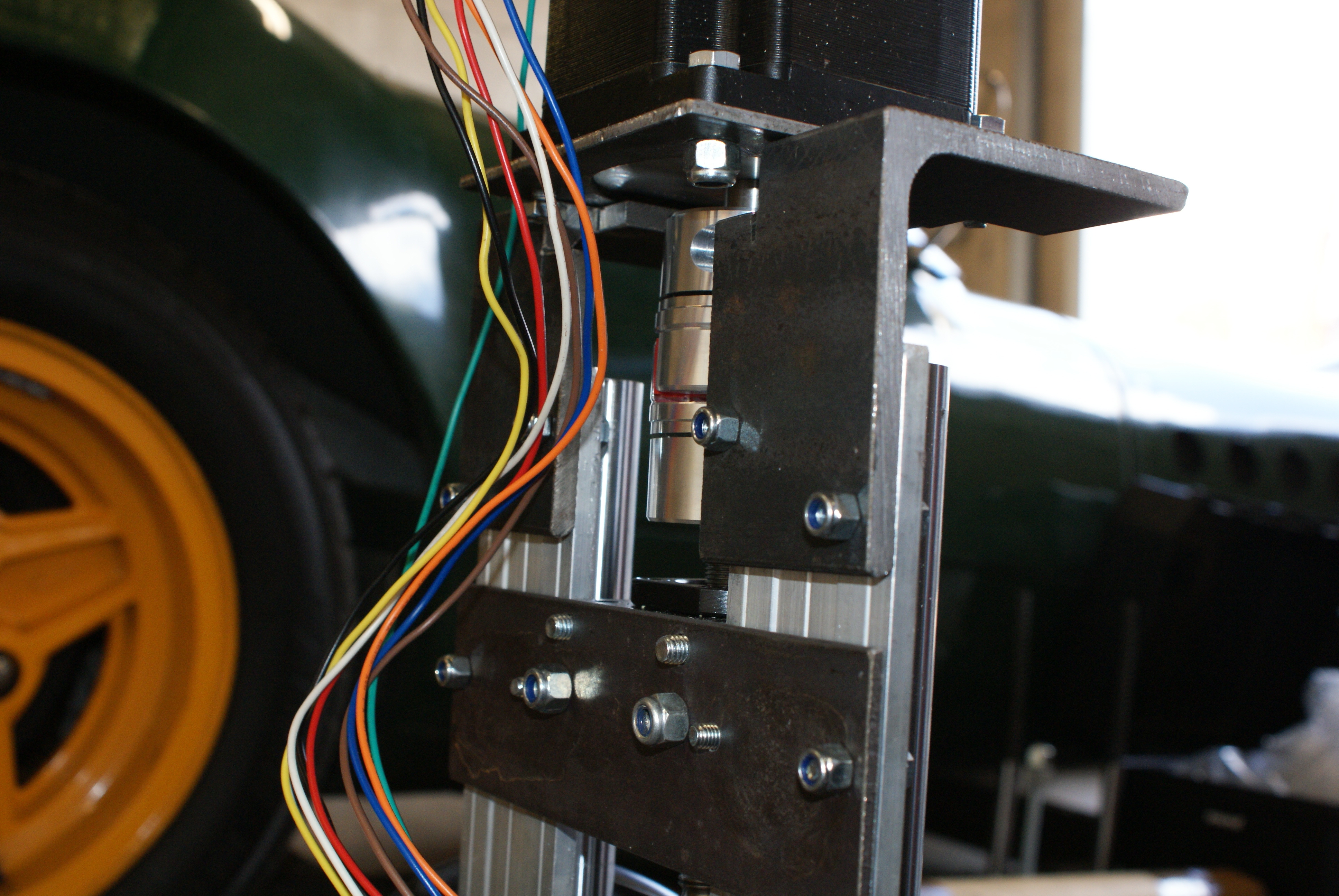
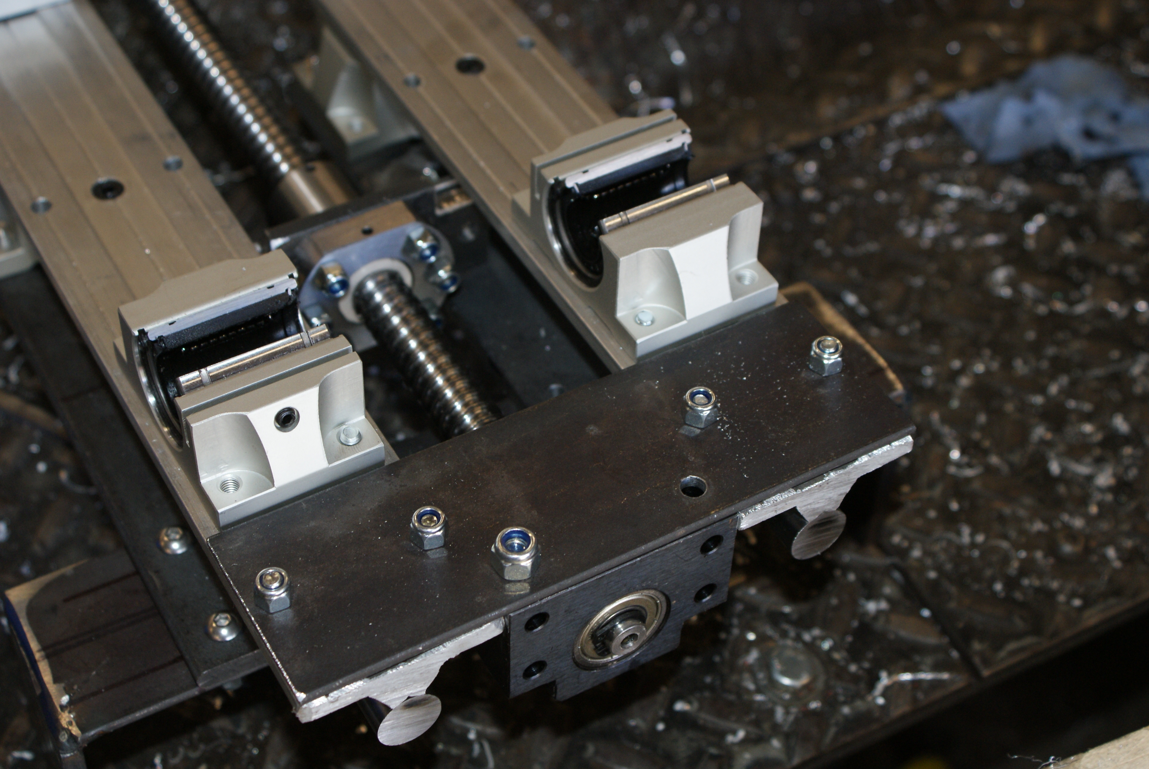
First of all, I welded some brakets on the back of the plate to attach to the ballscrew nut.
A couple of screws and nuts hold it in place:
This was what I wanted to finish off last night, but I didn't get the chance.
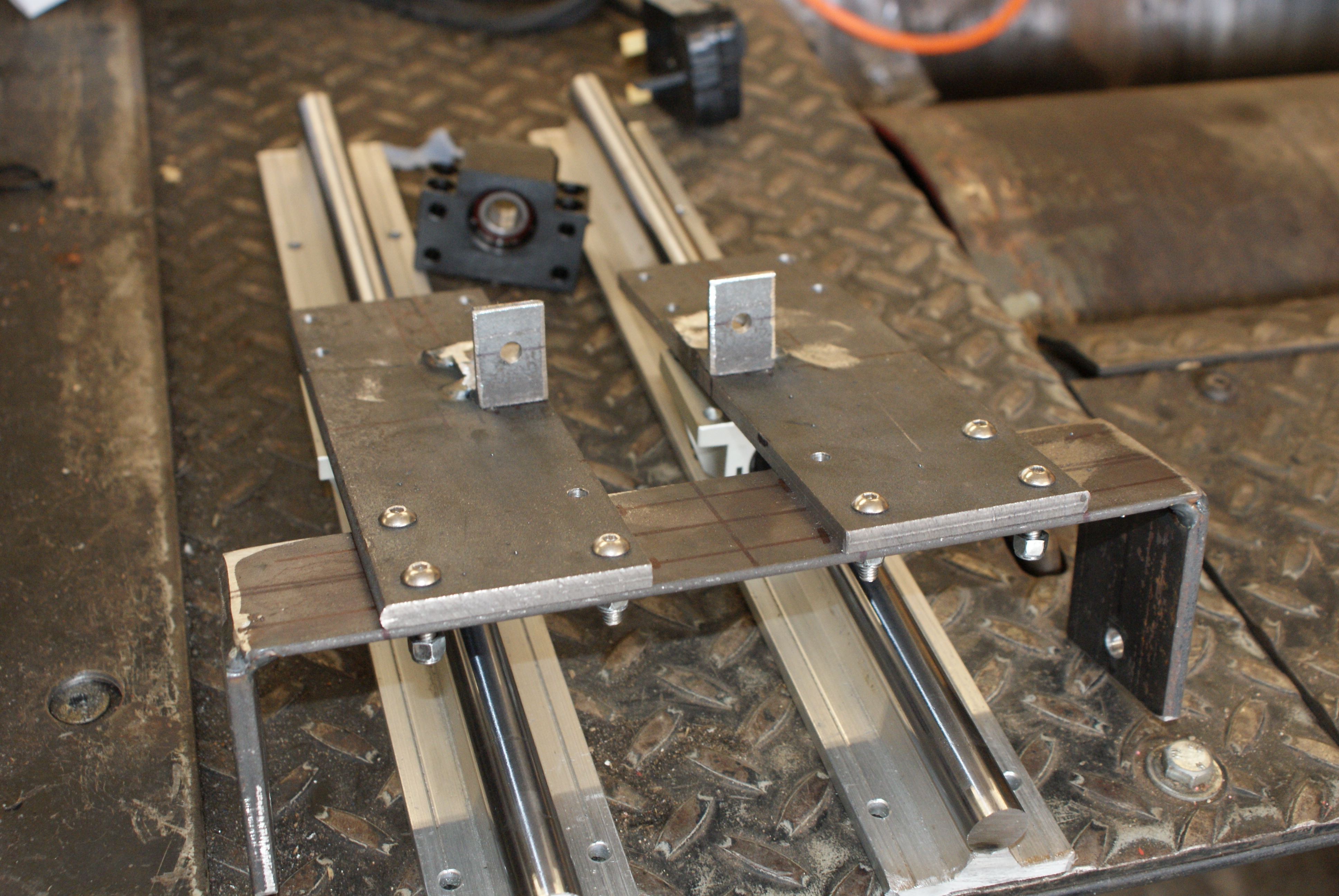
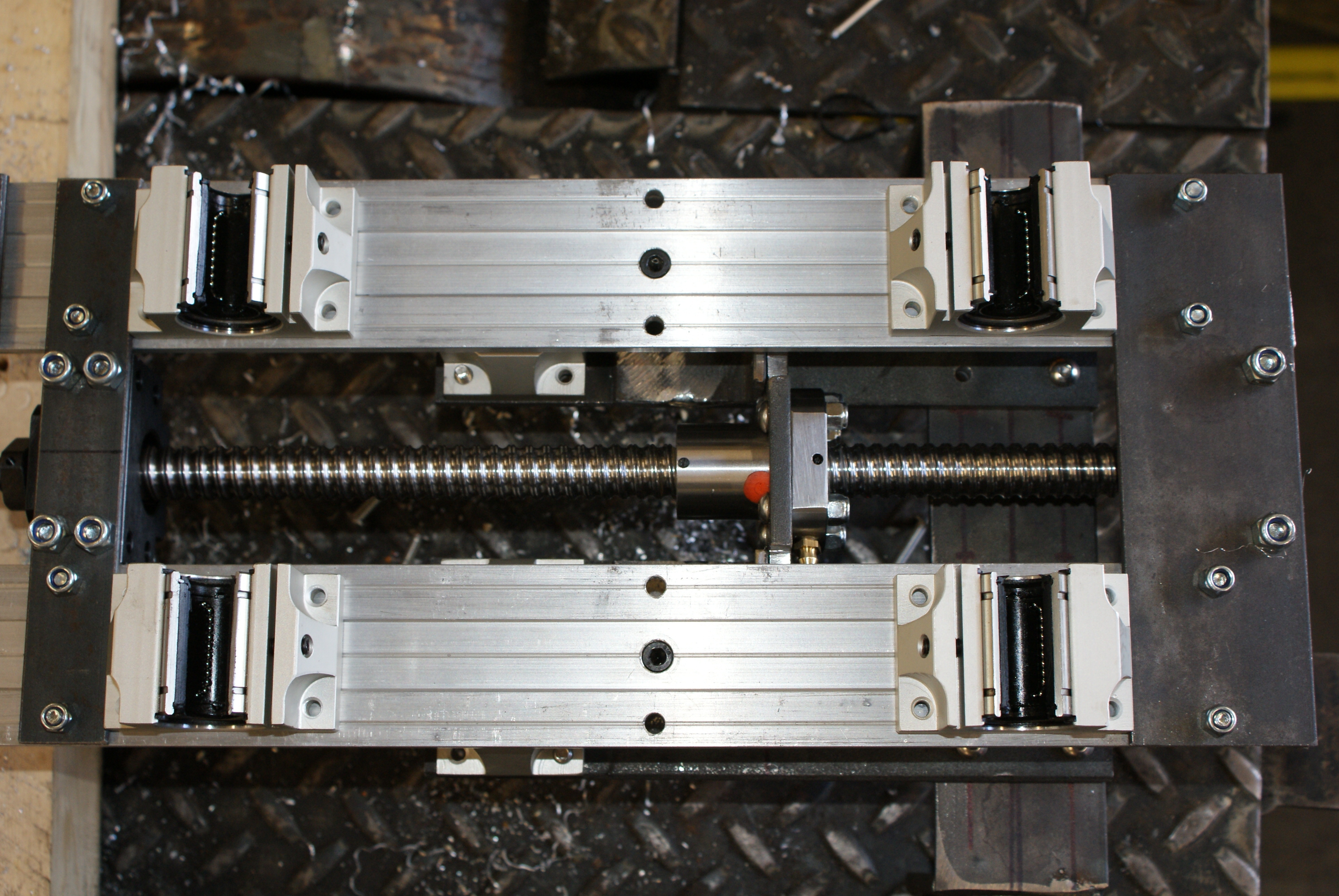
I then made a plate to hold the bottom of the Z-axis rails and ballscrew blocks:
And after making one for the top, it stood upright on its own:
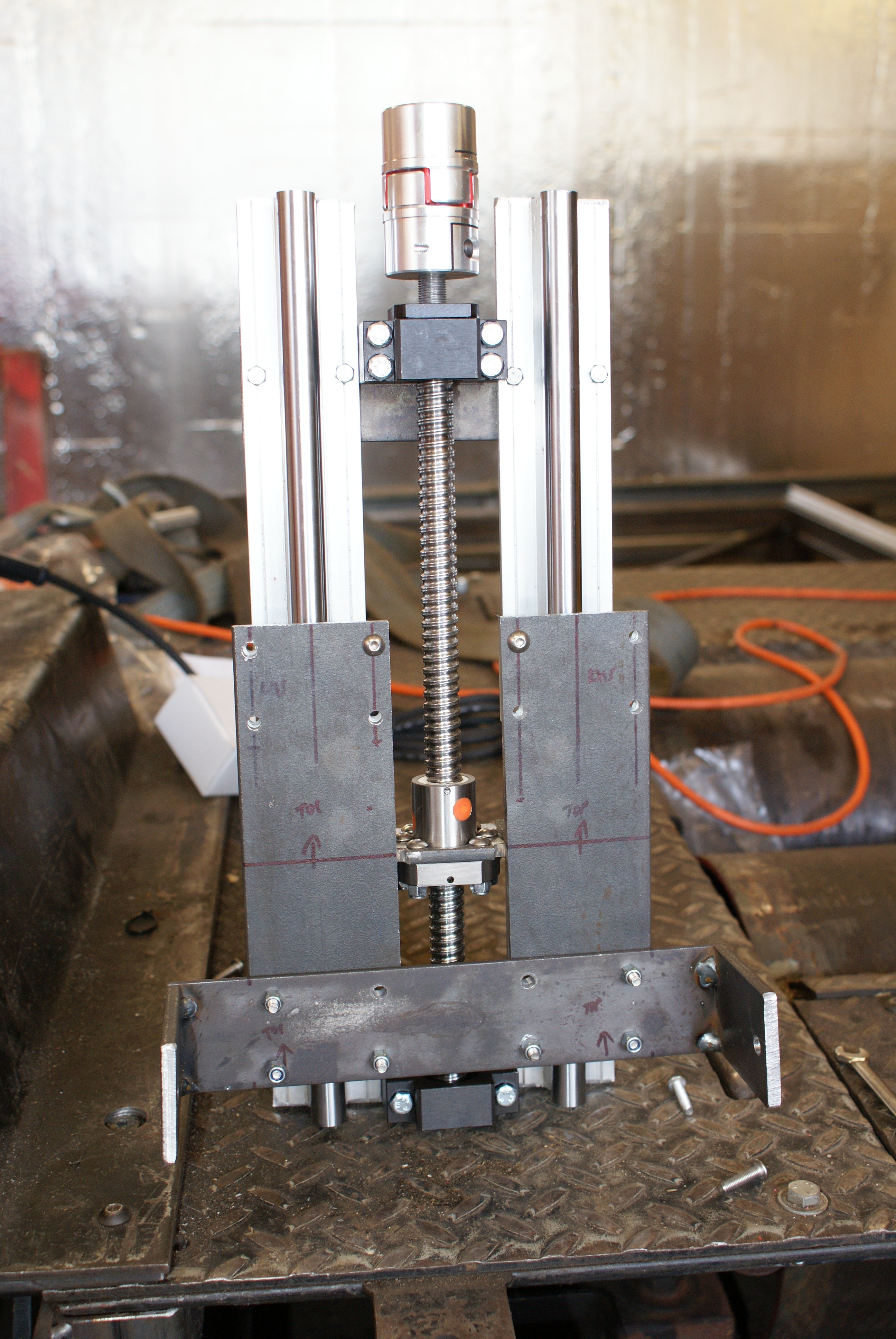
This picture shows the triangle formation of the two rail carriages and the ballscrew nut. This should prevent a lot of movement (this was questioned on the MYCNCUK formum), but if necessary, there's a bit of space under the existing carriages for a couple of extras.
Now, the motor mount - which needs it to be placed at the top:
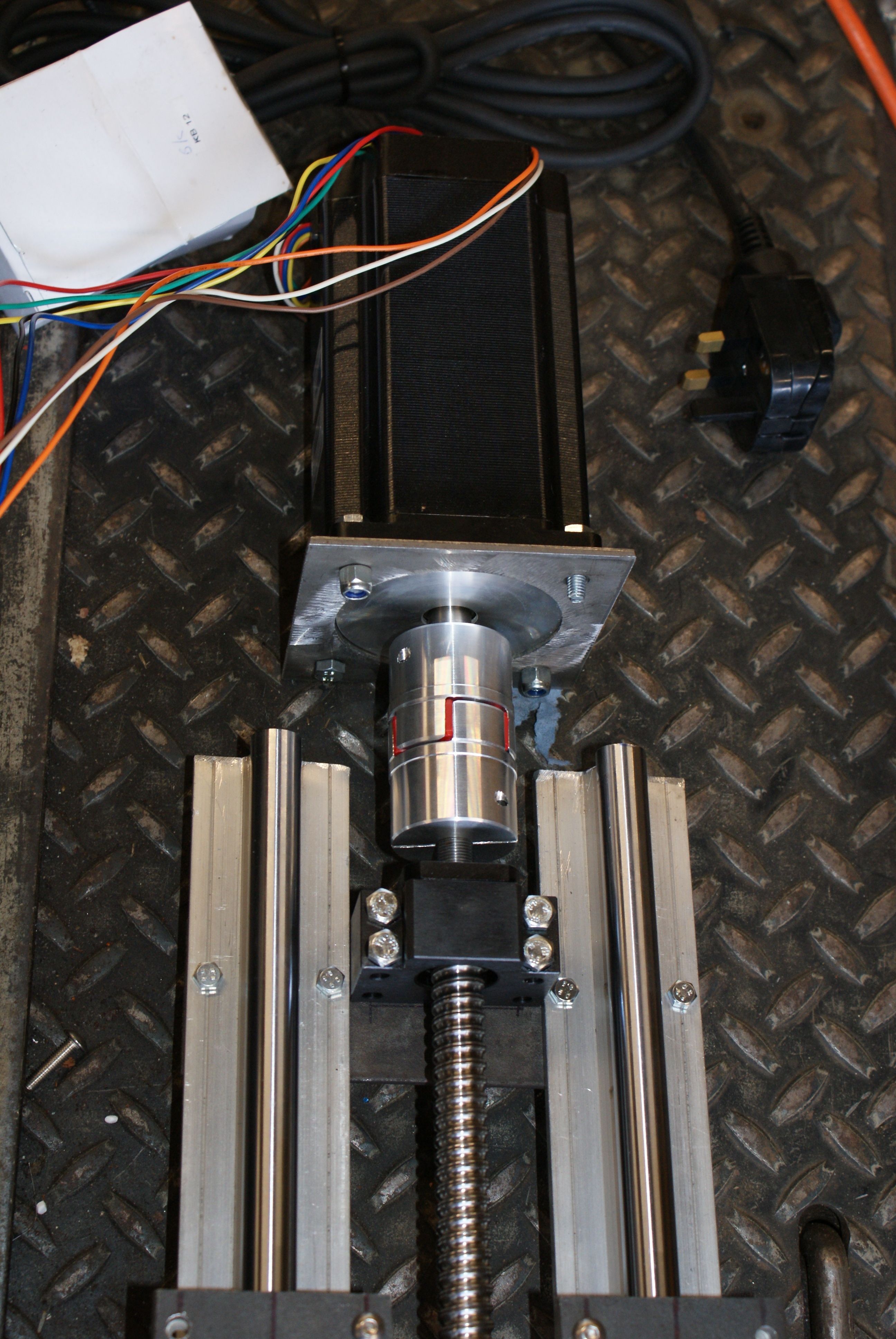
I made a NEMA-34 plate to hold the motor, and bolted some right-angle brackets to the rails (which needed some sections cut out for the motor mounting bolts.
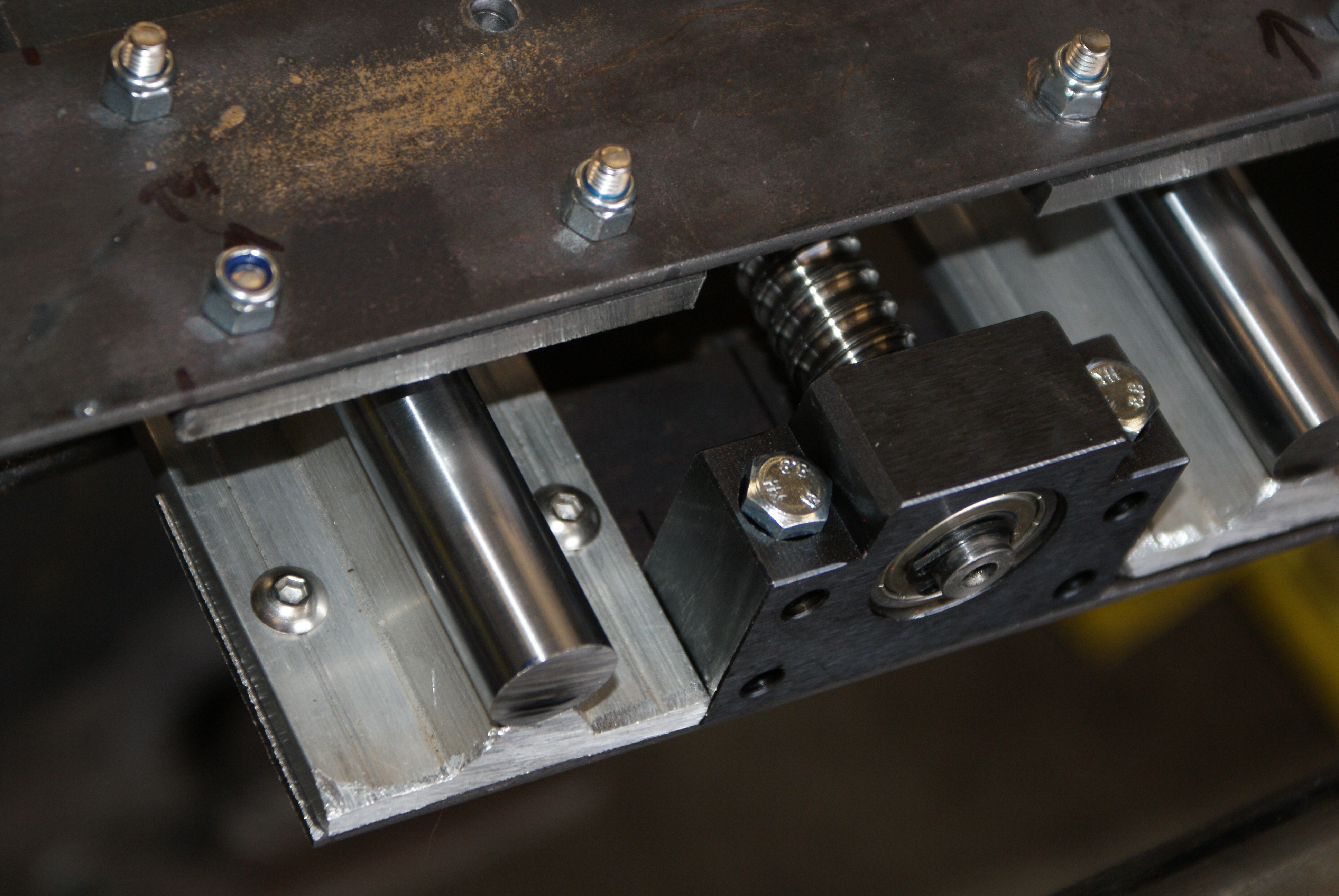
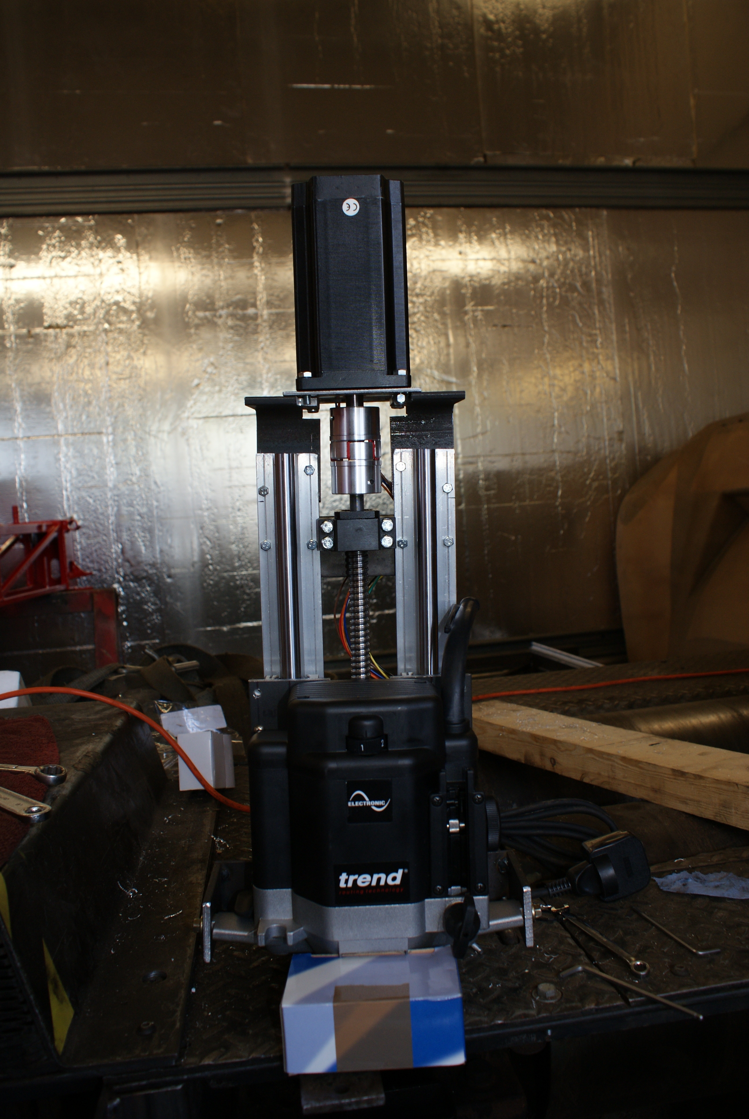
With everything fitted, the Z-axis is pretty uch done.
Since I'd finished the Z-axis a little early, I made a start on the Y-axis - the rail carriages are mounted to the back of the board, like this:
With the holes drilled, they're ready to be used.
The final thing I did for the day was to cut out the two pillars that will hold the Y-axis bars. Unfortunately, this is a bit dark, and it's probably the most boring picture ever taken:
Tomorrow, I'll cut out the two long bars that the Y-axis rails will be mounted to. I've also got a lot of the right nuts and bolts arriving (albeit to the office), so on Thursday, I'll start to replace them.