- Mechanical
- Steel
STLCutter 2 - Day 17
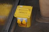
My 110V converter got acquired by one of Keith's guys because theirs went wrong, and mine was idle. So, I bought a new one (or rather Keith bought me a new one), and tried to ensure it remains mine:
I wired up the Y and Z axis motors to the drivers...
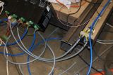
...and also the laser
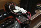
I needed somewhere to put the parallel port interface, and decided that attached to one of the drivers would be fine (it doesn't get hot, so shouldn't affect it in that way). I also got a relay I'd bought back in October, and wired the router's supply through it (although this is out of focus - it's to the left of the drivers).
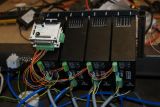
In order to ensure that both X axis motors span in the same direction, I attached some cable ties to them:
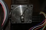
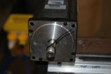
And I was quite relieved to see that they were spinning in the same direction (I didn't expect them not to, but then some oddity may have occurred, and I would have to work out how to reverse one of them by switching wires around).
I then drilled the holes for the connecting blocks - they needed to be 15mm. One of the earlier attempts had resulted in a hole that was 15.5mm - slight too large due to a bent drill. Since I knew Keith had two 15mm drill bits, and I had one spare connecting end, I should be okay.
The hole I'd made was 15.2mm - which was fine, so I drilled the second connector. And then attached them:
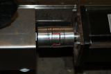
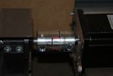
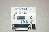
One thing I hadn't taken a picture of was my test unit. It emulates the PC parallel port, so I don't need to power up the PC in order to make the machine move. Unfortunately, it's very slow, but it's good enough to make sure that they're all moving in the right direction.
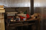
I then needed some space for the computer and monitor. There's a bench in the corner near the driver end of the machine - although it's the only corner of the room without any power sockets! It also needed a bit of clearing:
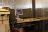
After a few minutes of clearing, putting a sheet of MDF over the (very) rusty surface and setting the computer up:
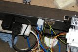
And as a final stage of the wiring, I attached the relay to the parallel port interface:
I made sure that all the nuts and bolts were tight, and then did some test movements with it. One of the EMC tests for configuring the stepper motors is to vibrate it. When I'd got the machine basically running last year, it showed that having only 1 X axis drive was not accurate enough, as the other end wobbled out of phase with the motor (hence this additional phase moving things around, and putting in a second X axis drive mechanism).
This moved wonderfully, so I'm happy with the changes that have been made.
And that's basically the machine finished. Tomorrow, I'll start painting it (white and red will be its colour scheme), and we'll then be able to start doing some work with it (although we will need to get a sheet of MDF for the bed first).
I'll also do a bit of cable tidying, and I may put some wheels at one end so it can be lifted and then wheeled around if necessary.
