STLCutter 2 - Day 5
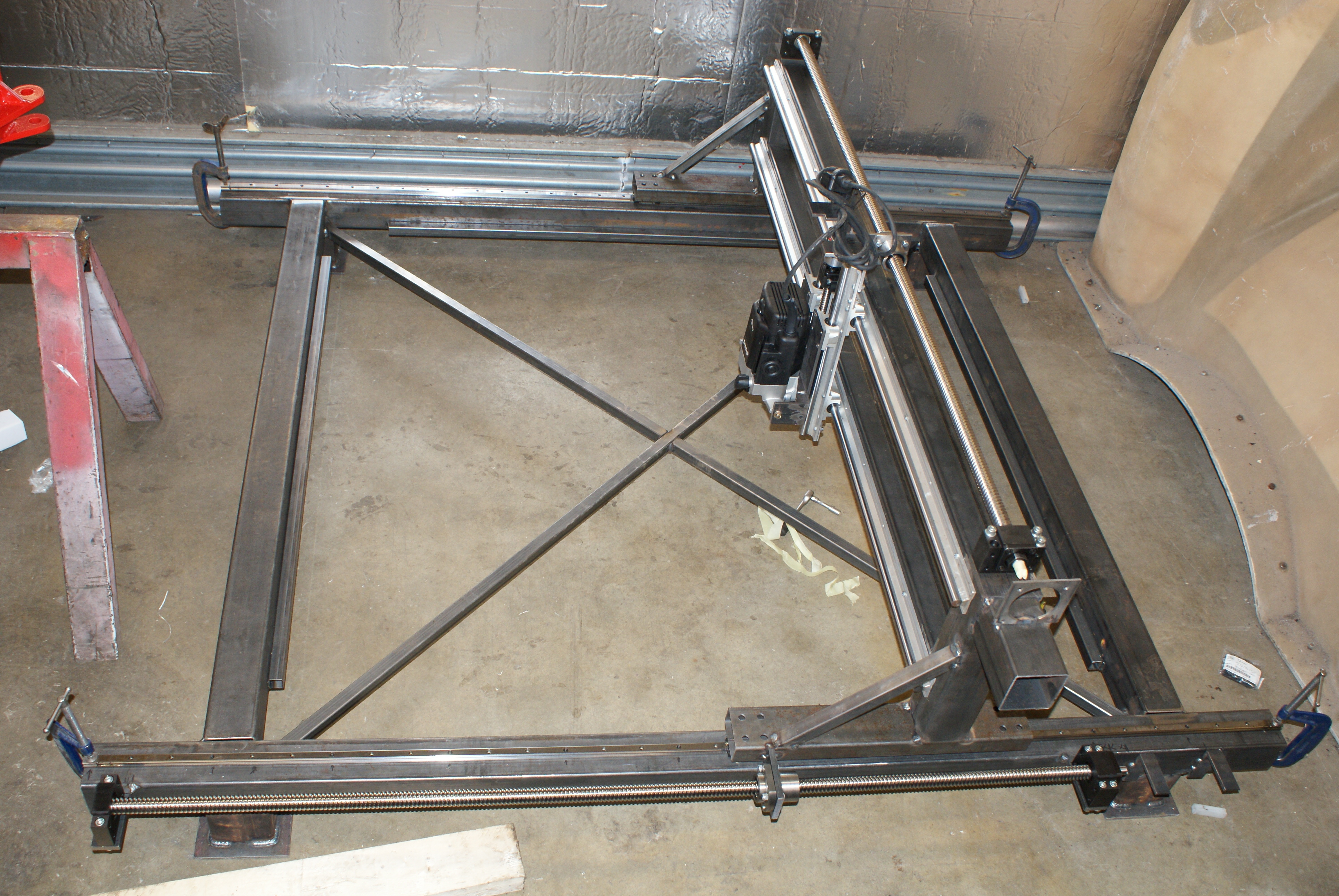
Today was luckily a dry day, so I took the Aeon to the workshop. I now needed to do work with the frame that was made earlier.
The idea was to make it look like this:
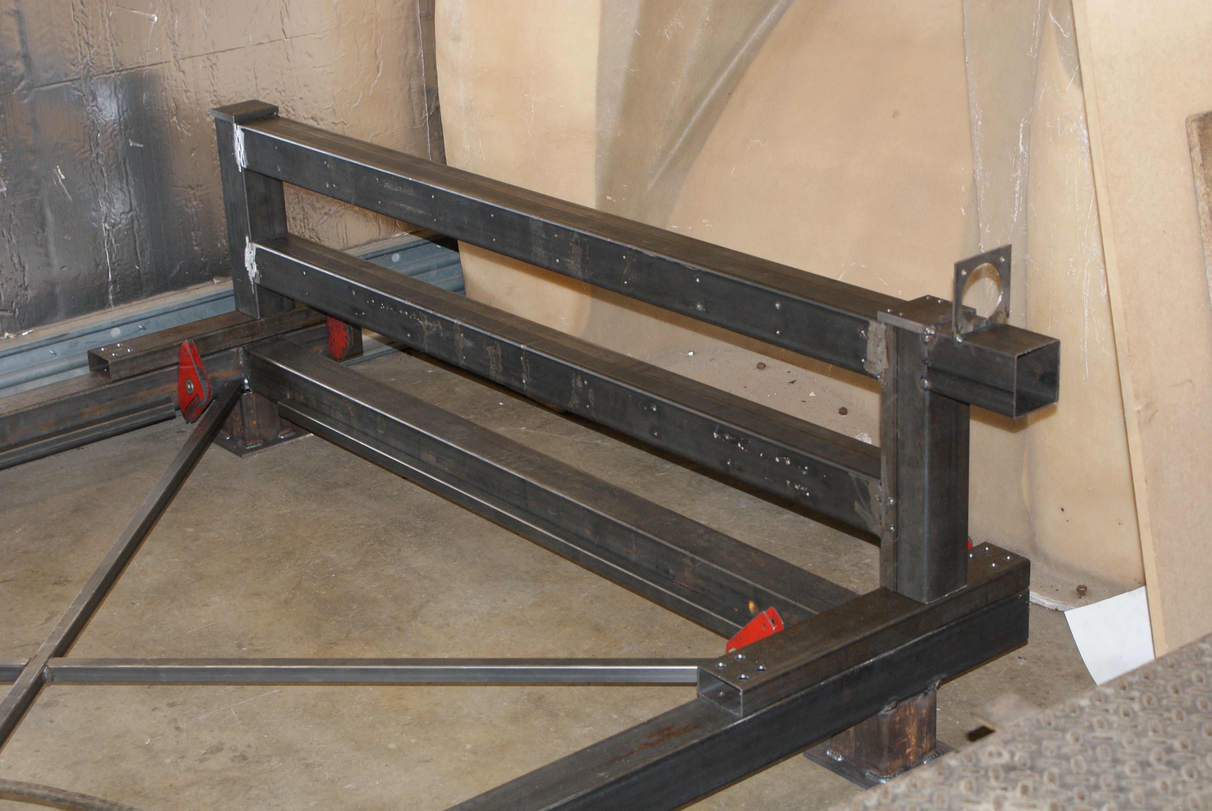
The welding clamps made sure they were straight, and I measured from the back of the foot to the vertical section.
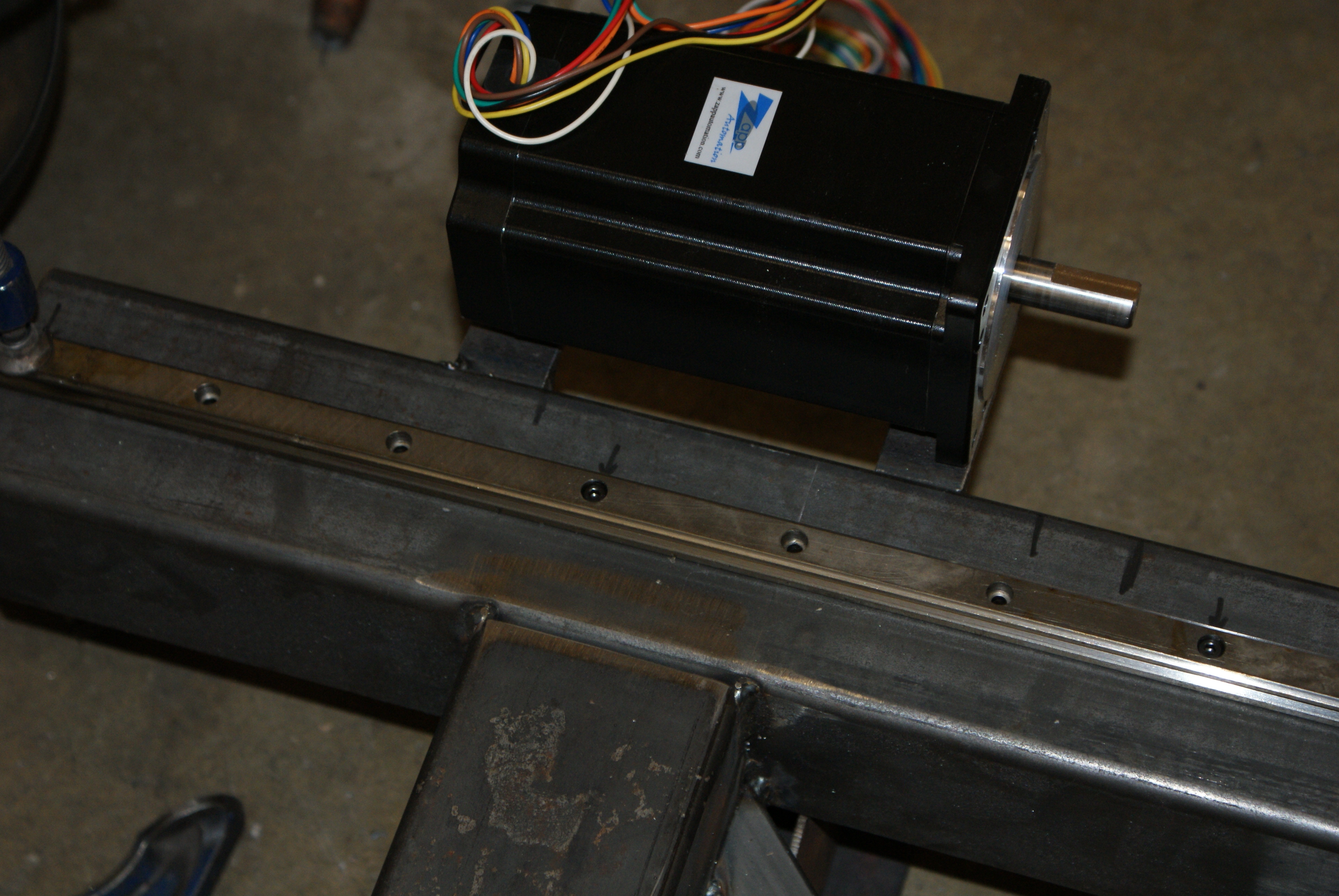
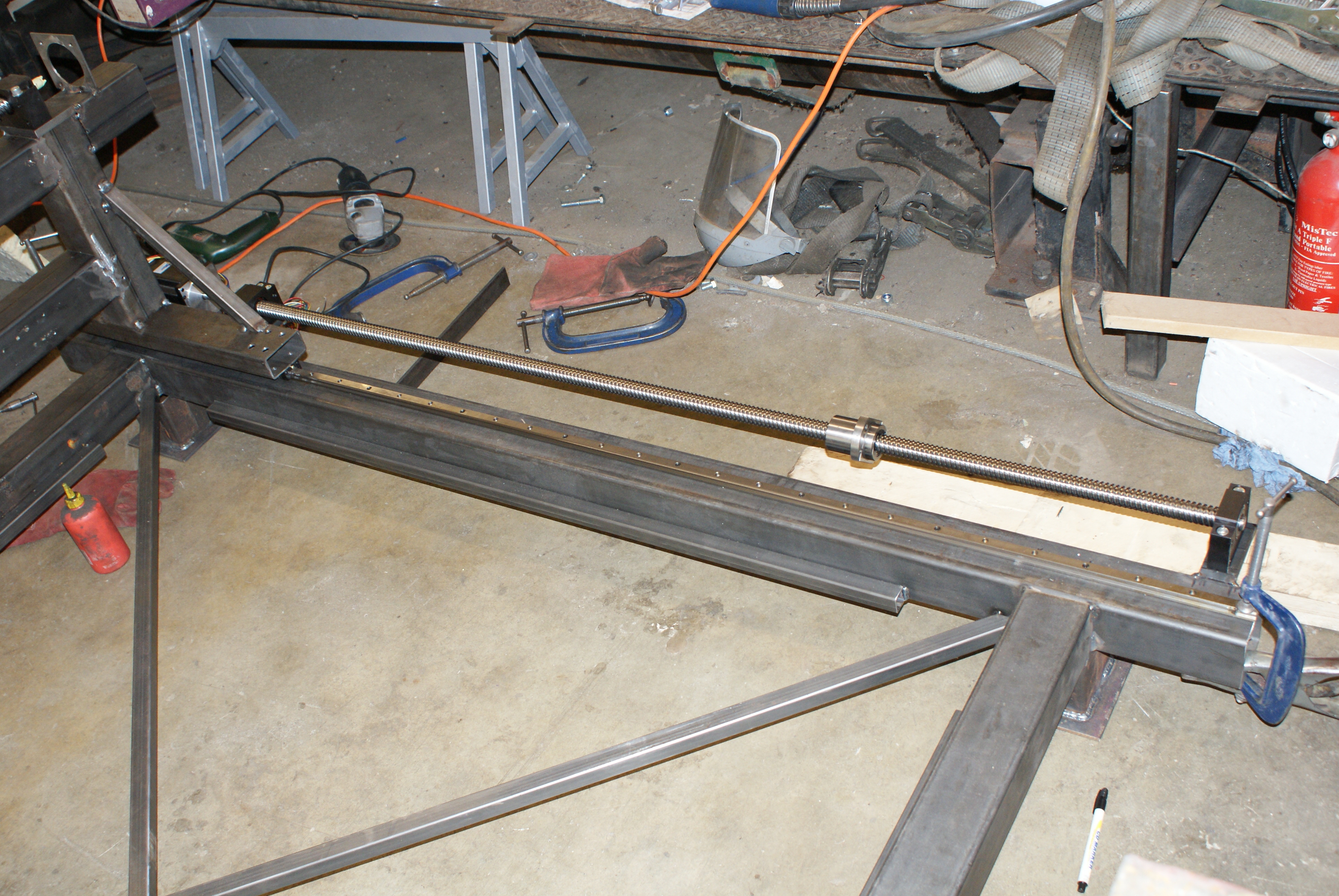
After welding it, I put the carriages on the rails, and then bolted the Y-axis frame to the carriages.
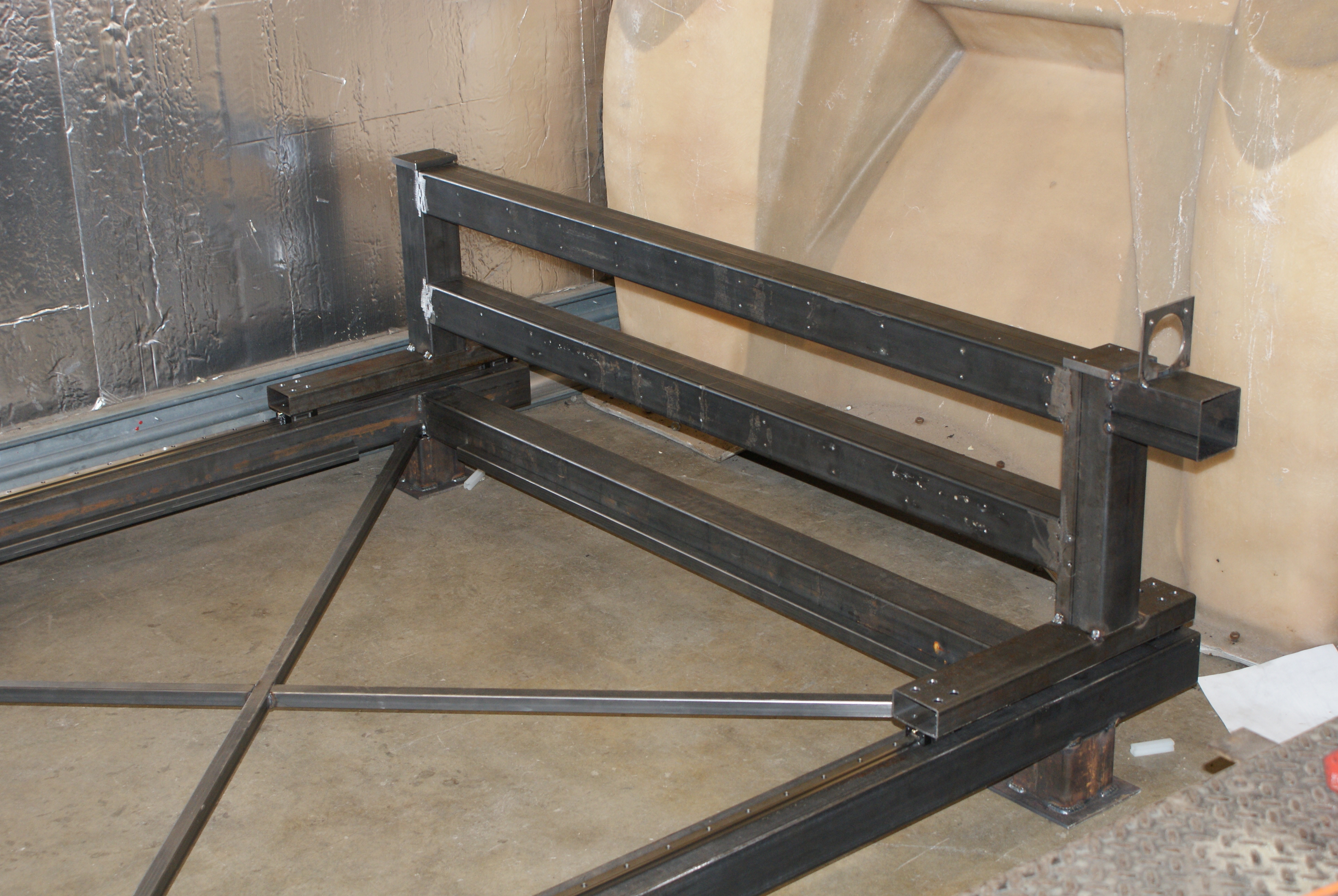
It glides very smoothly!
I added some braces to give it a bit more strength (although I've no idea why the picture ended up so dark - I think I was using a long zoom).
Since there isn't a lot of horizontal force on the rails, I only bolted one every three - which happened to give a symmetrical pattern (quite by accident).
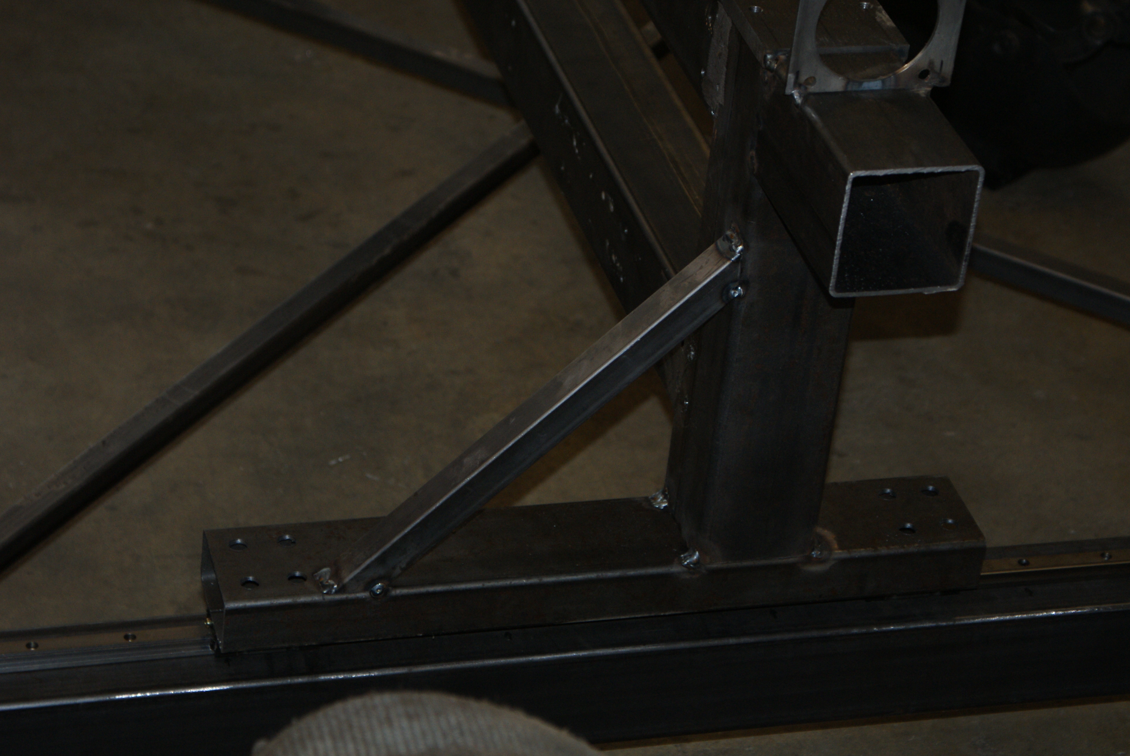
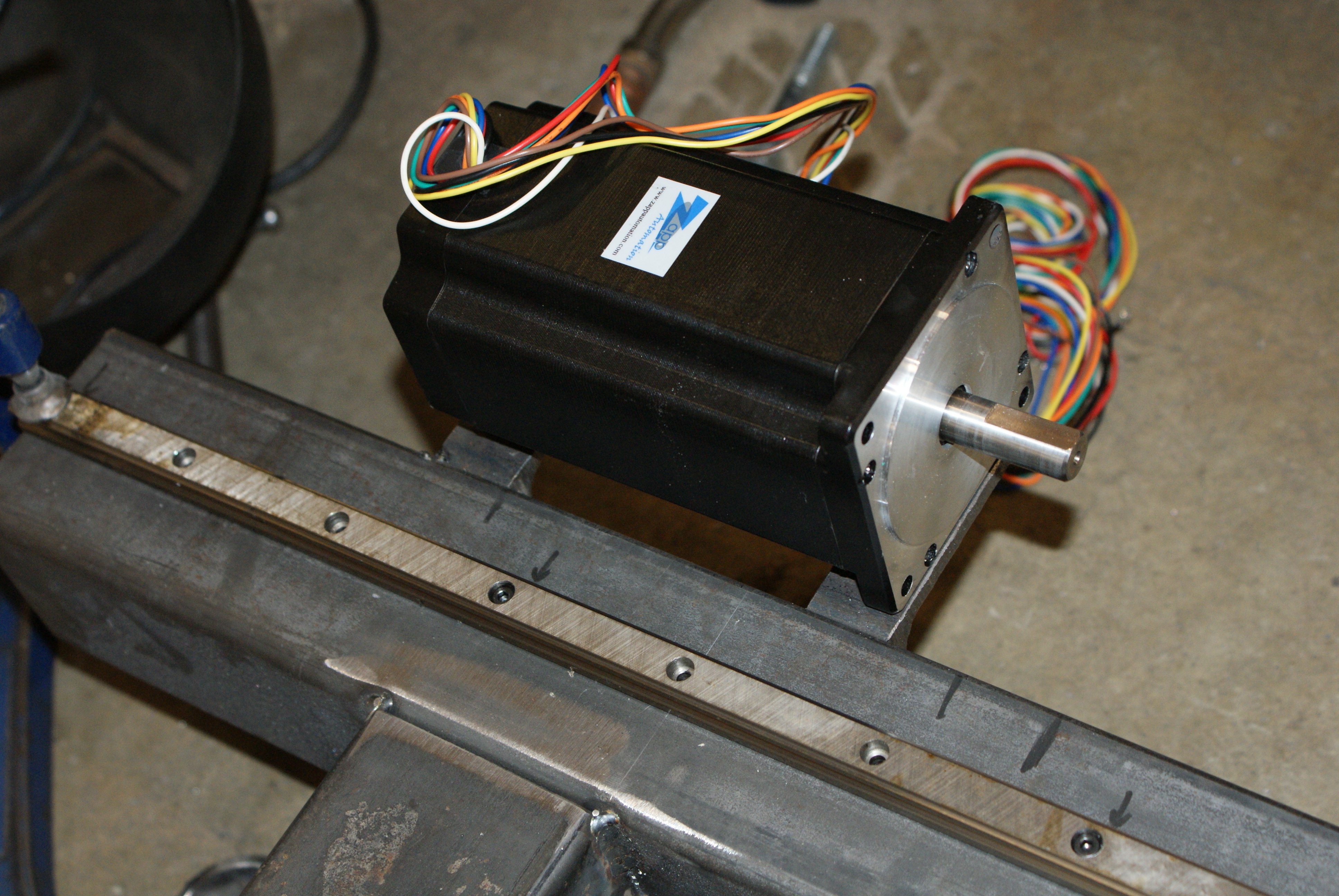
The next stage was to make the motor mounts - I used some right-angle steel, and welded it to the side:
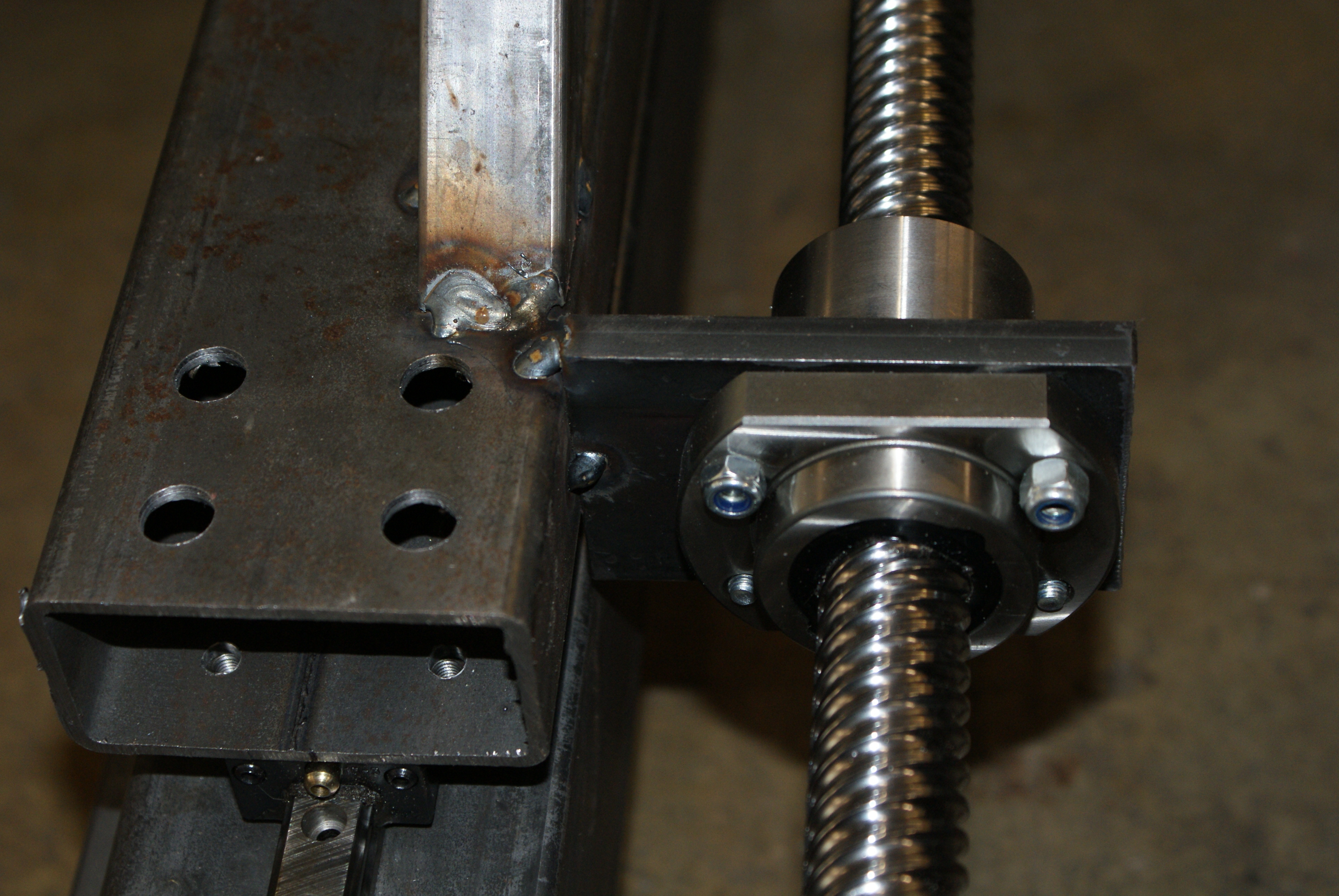
And then some thick flat bar was welded to fit the ballscrew bearings.
I may make an alumimium cover for it in case it gets kicked (it's very low).
For the ballscrew attachment, I did a similar thing for the Y-axis, except I welded the plate instead of bolting it (this is only tacked on; it'll be welded more thoroughly later on).
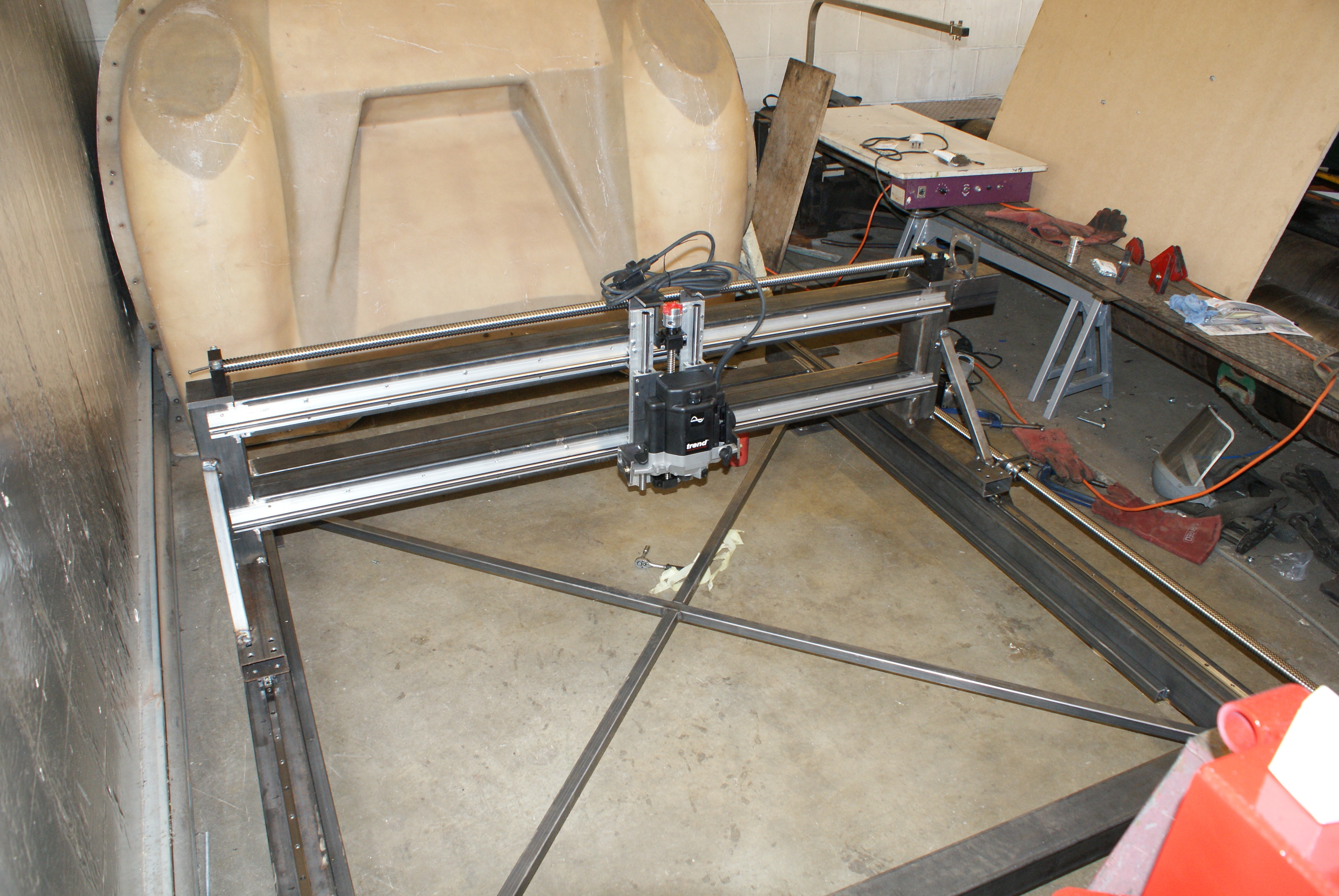
Finally, I attached the Y-axis rails and Z-axis unit back onto the Y-axis frame to see what it looked like completed:
I did have a slight incident which almost caused me to abort during the manufacturing of the ballscrew plate - while drilling a 48mm hole, the drill suddenly made a crunching sound. I found I'd ripped half the teeth off the hole saw.
Luckily there was another one, so I continued with that - however, I hadn't realised the remnants of the teeth were still in the hole, and promptly ripped a few off that one.
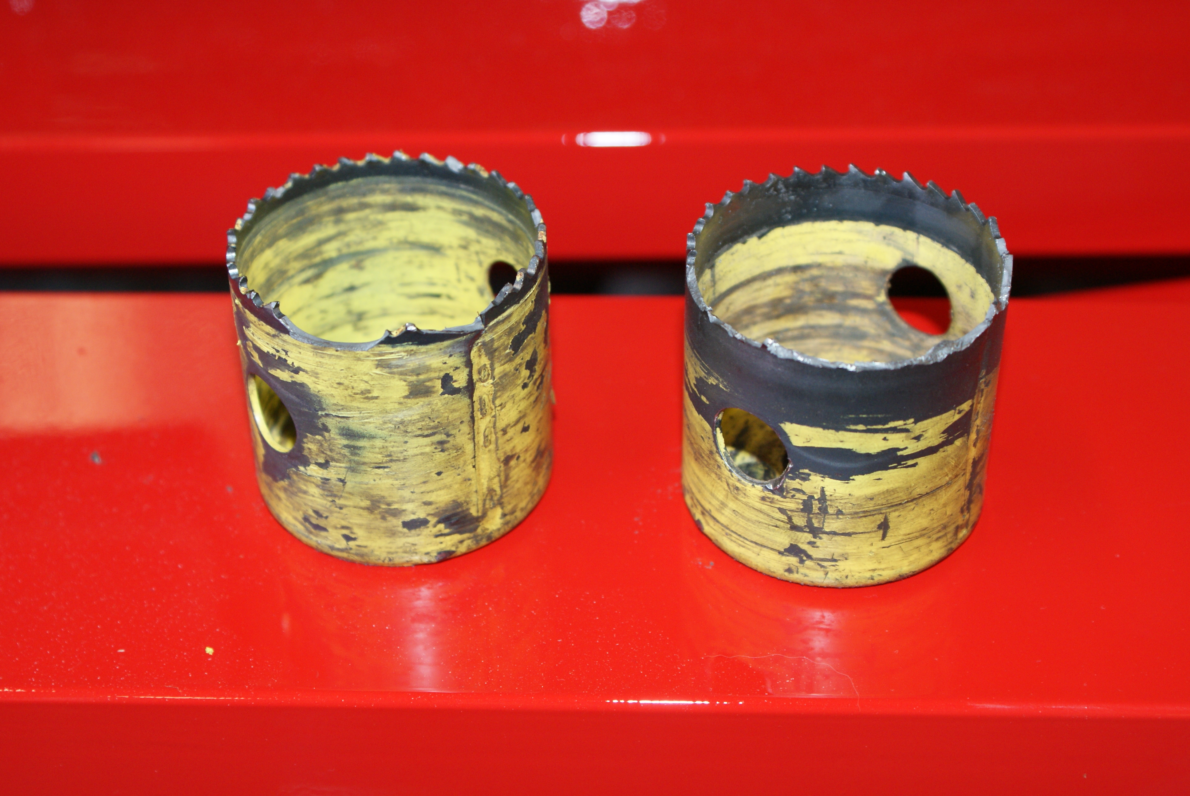
There were enough for me to finish off the hole from the other side though. And luckily, Keith doesn't seem to use the 48mm hole cutters, so I don't need to immediately go off and buy a new one.
So, I'm reasonbly on schedule - the plan had always been to spend 2 days on each axis, apart from the X-axis, where only one would be required (since the frame had already been made). Next Monday, I was planning on starting to wire it, but there's some finishing off to do (like making a new Z-axis motor mount, and also an X-axis motor mount, tidying up the welding and making cable supports).