STLCutter 2 - Day 8
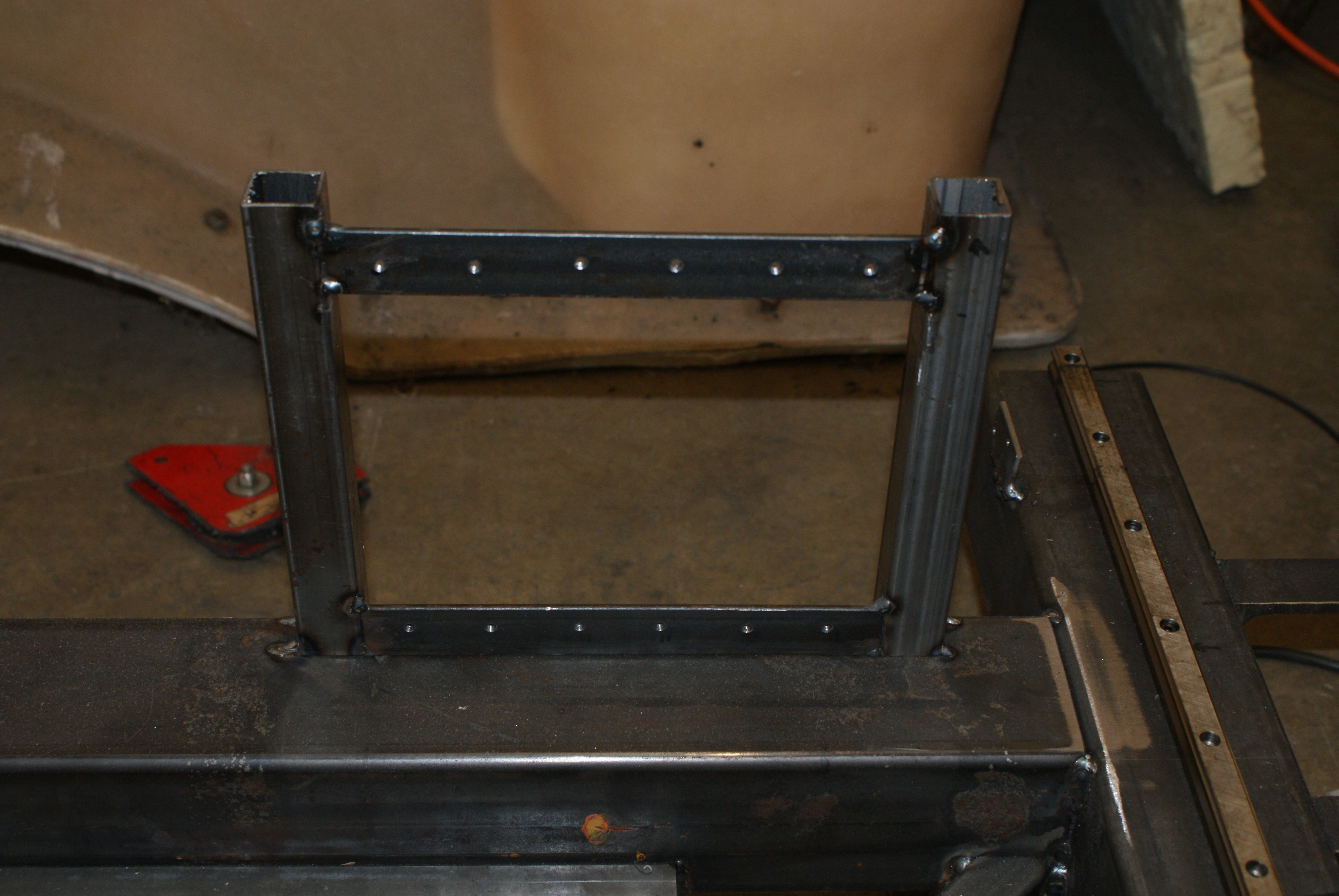
Overnight, I decided to mount the motor drivers on the frame, so I wouldn't need to have long cables carrying the current for the motors.
I made a small frame which I drilled and tapped for the drivers:
Last month, I used a 19" panel in order to hold the printer port interface, a 16x4 LCD display (to show the current position), the three drivers and a computer LCD display.
The 16x4 display is controlled by a PIC which also monitors the charge-pump from the software, and can emulate the limit and home switches, as well as control the motors itself (it can take 4 analogue and 4 digitial inputs). I may at a later date put in something that allows it to measure the height of the tool for automatic Z-axis homing.
I was going to use the panel and just mount it - however, the panel really needed to mounted in a different way - however, the half that holds the 16x4 display was still useable.
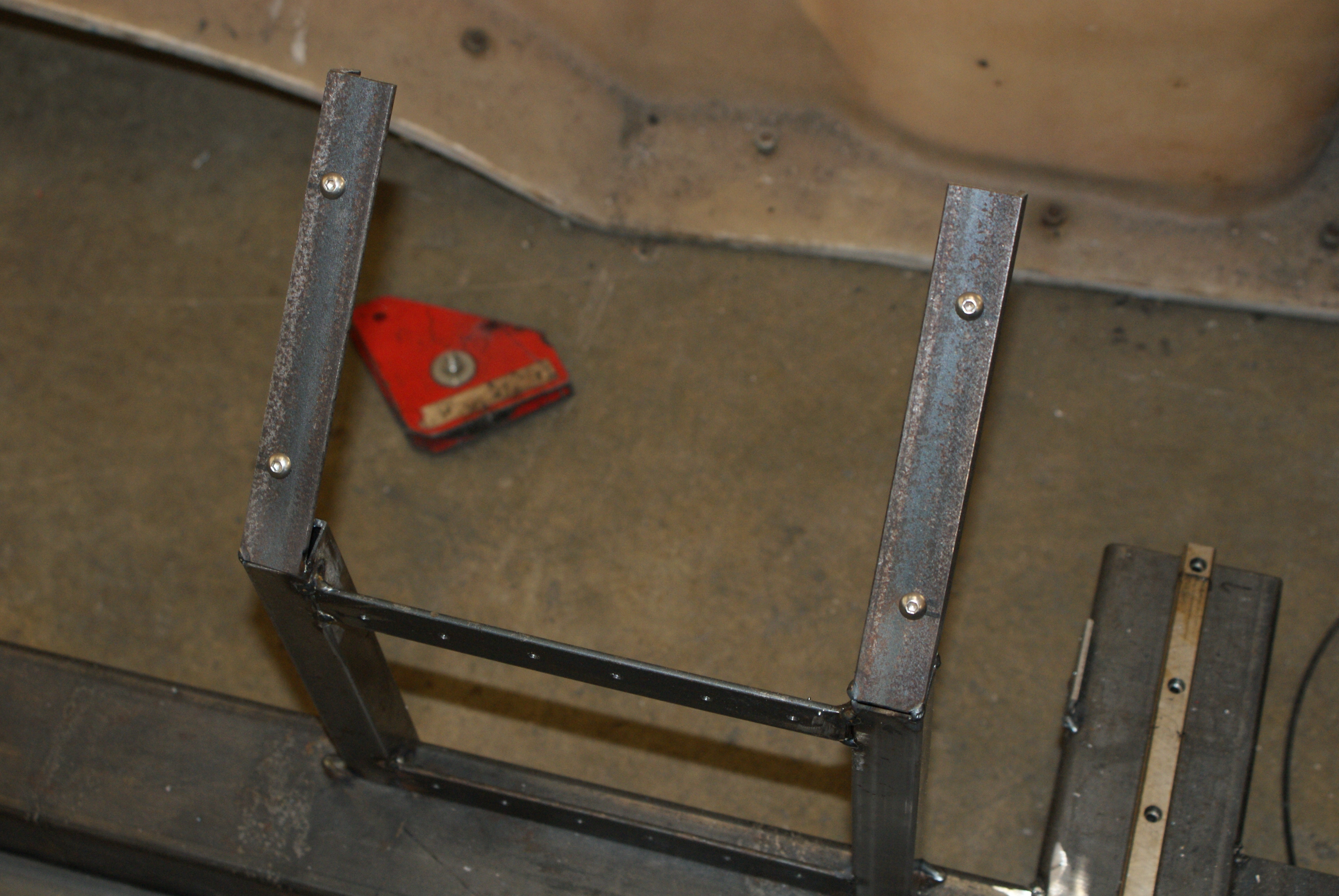
I welded extra right-angle bars to the driver frame:
And with everything mounted:
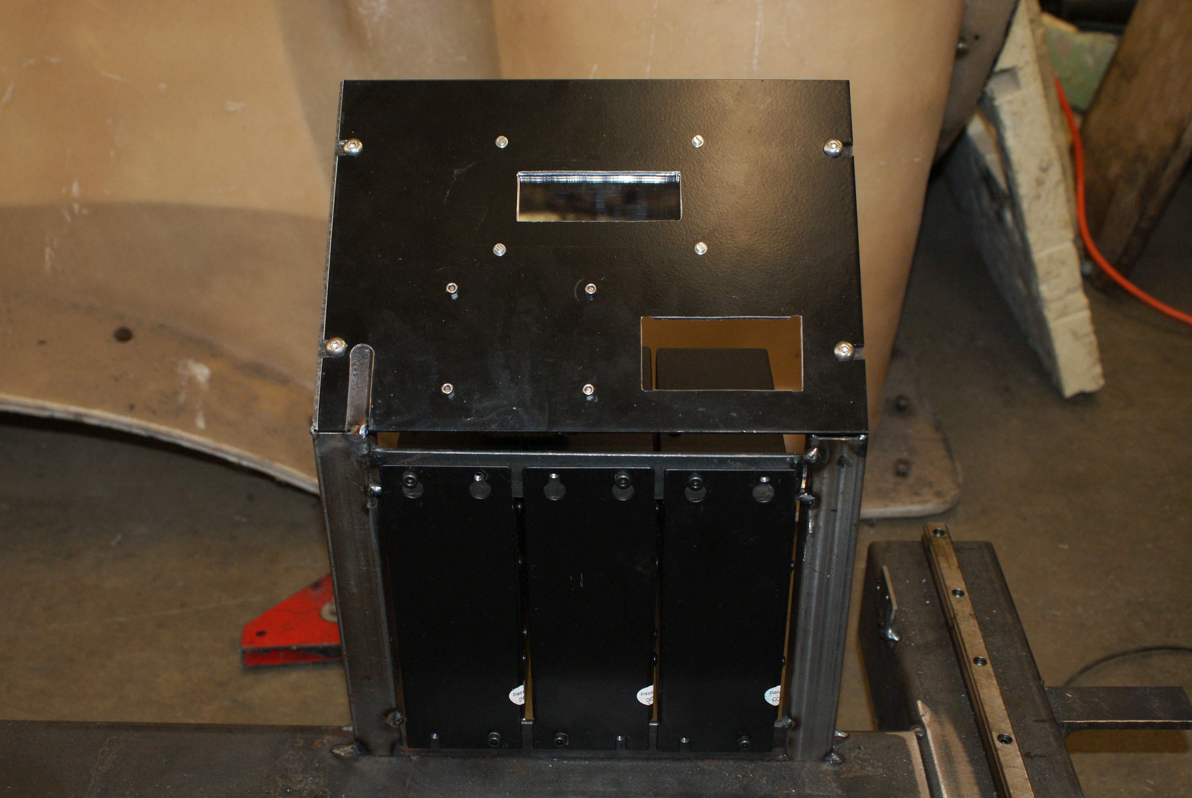
The hole to the bottom right was for a switch, and the slot to the left was for the LCD cable. I'll make a new panel when the machine's finished - in fact, I've got ideas to get it to make parts for itself to improve the look...
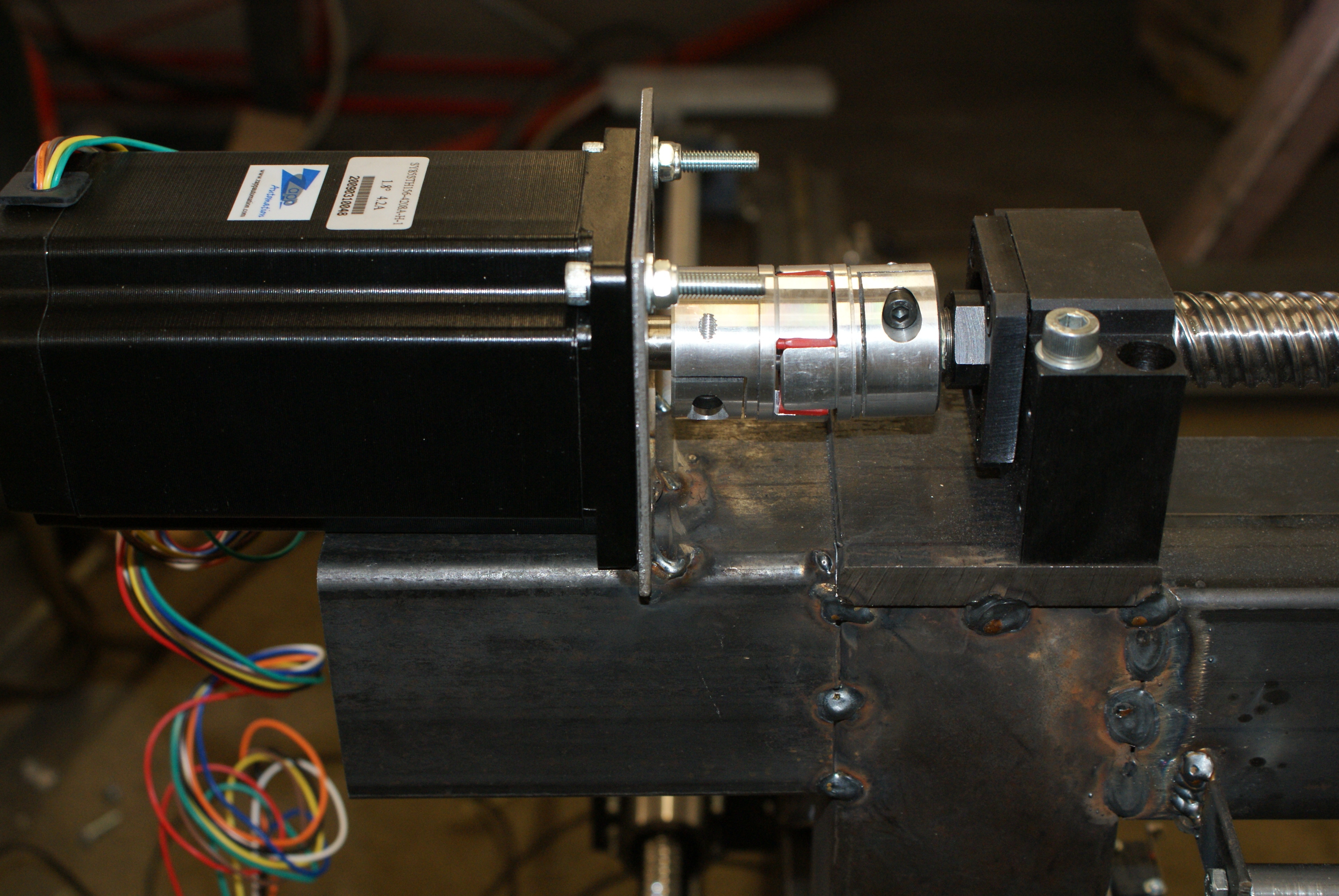
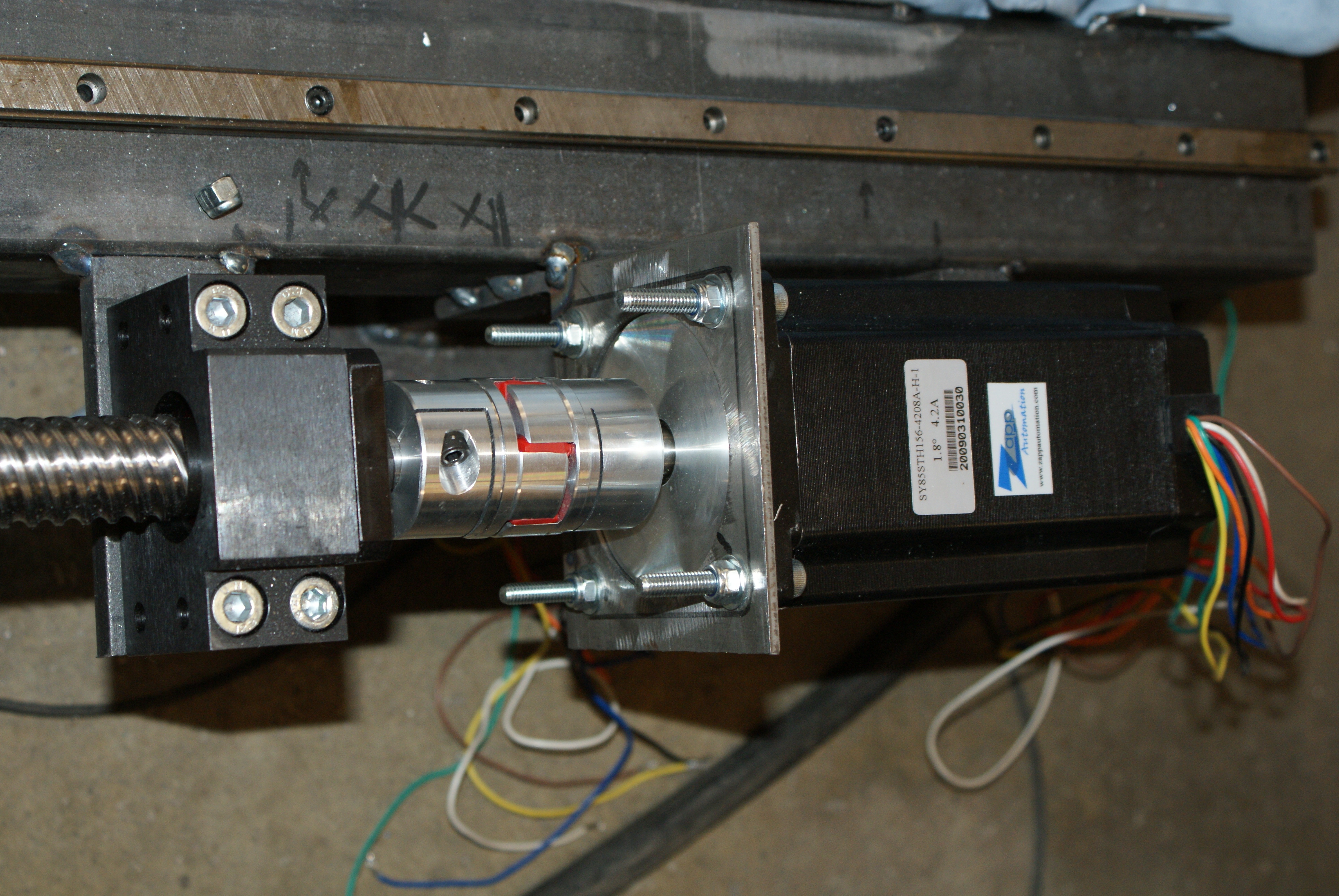
Now the motor couplings had arrived, I needed to drill one side to 15mm for the X and Y-axes. Unfortunately, I didn't realise that the first 15mm drill bit was a little bent, and it actually drilled a 15.3mm hole (and it didn't want to grip the shaft). Luckily another 15-mm drill bit was straight, and the other one was fine.
For the one that was 15.3mm, I wrapped some tape around the shaft and gripped it there - hopefully it'll hold (I put it on the Y-axis, which doesn't need as much torquea as the X-axis).
As I was now able to connect the motor to the shaft, I could put the motor mounts in the right place. The Y-axis:
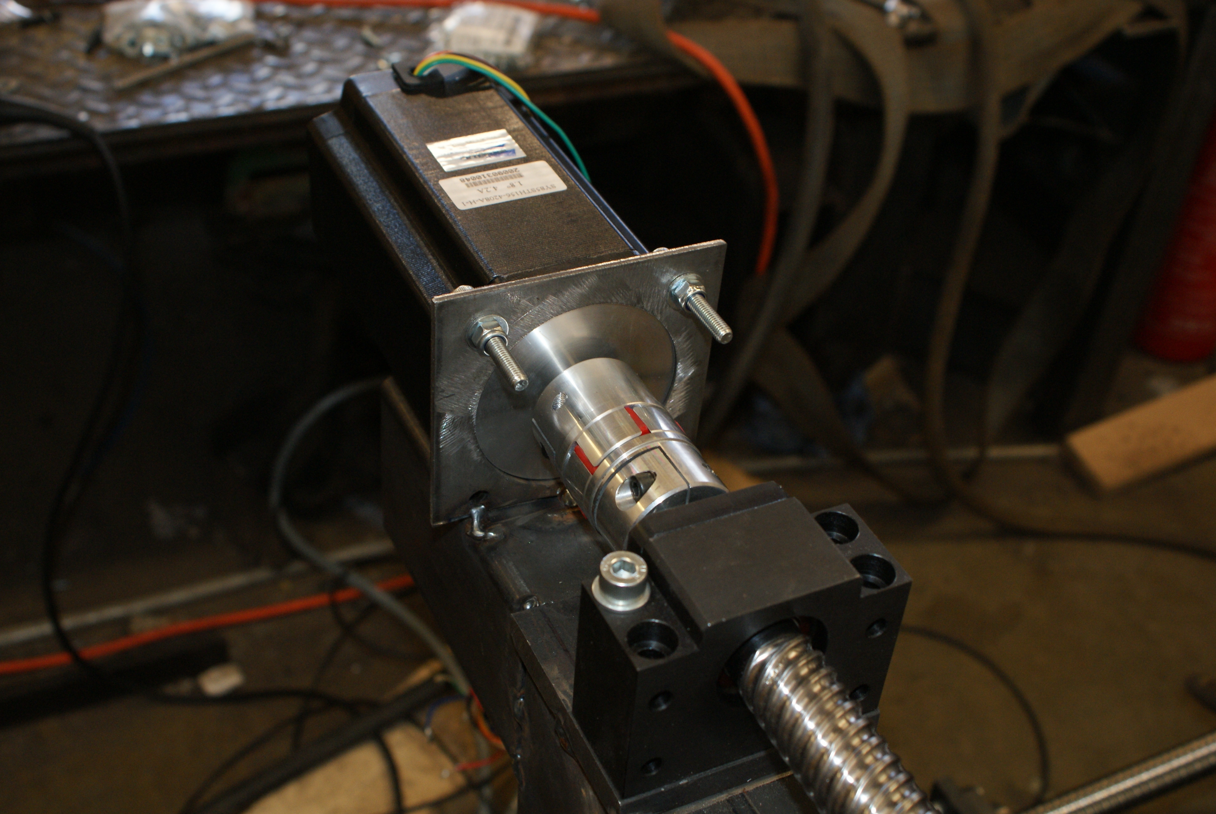
And the X-axis:
I then went about wiring the motors - I'm using chocolate-block connectors so I can easily fix it if I accidentally wire it incorrectly, or if I want to switch from parallel to unipolar mode.
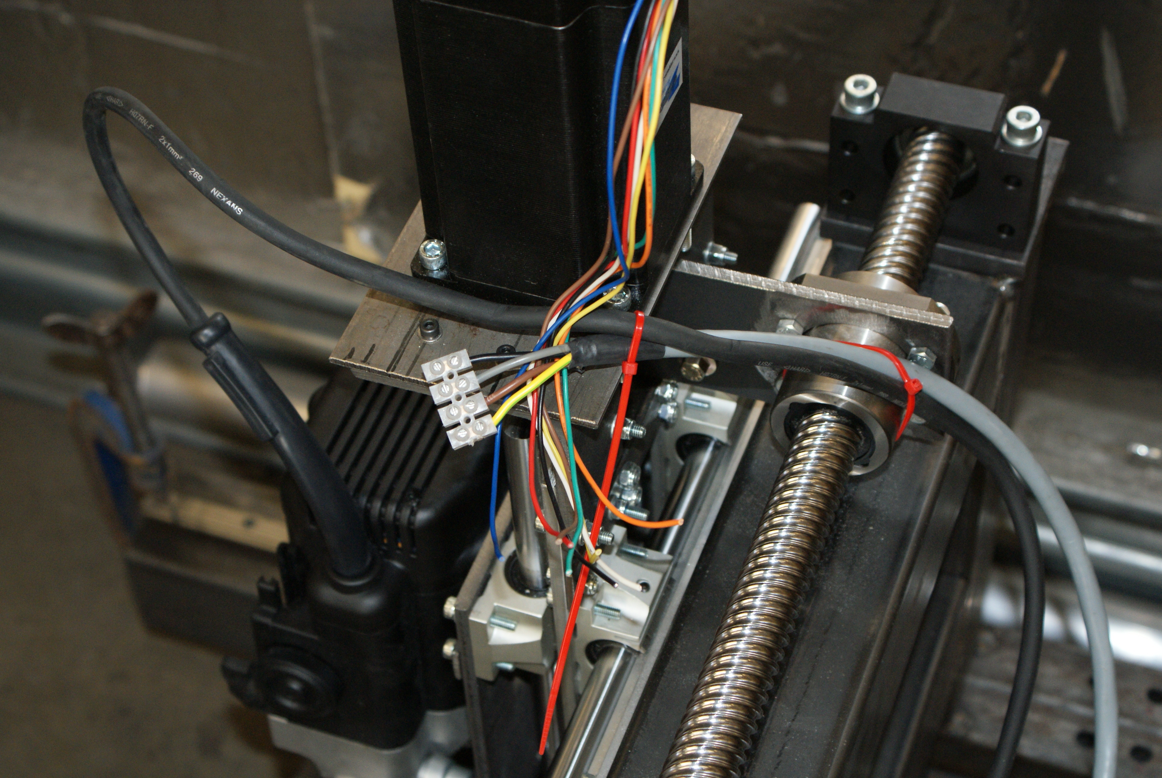
The Y-axis also has the same wiring:
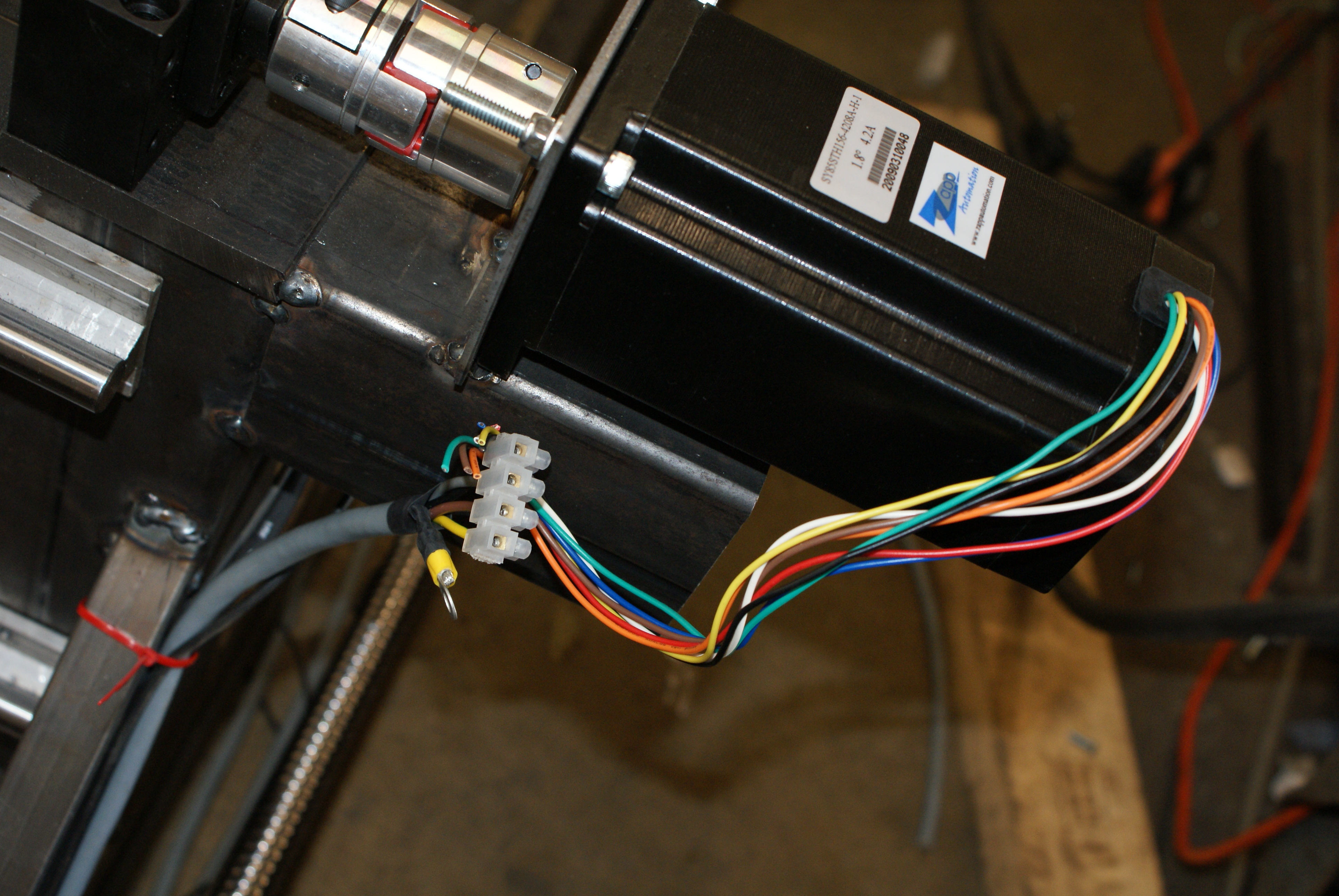
As does the X-axis:
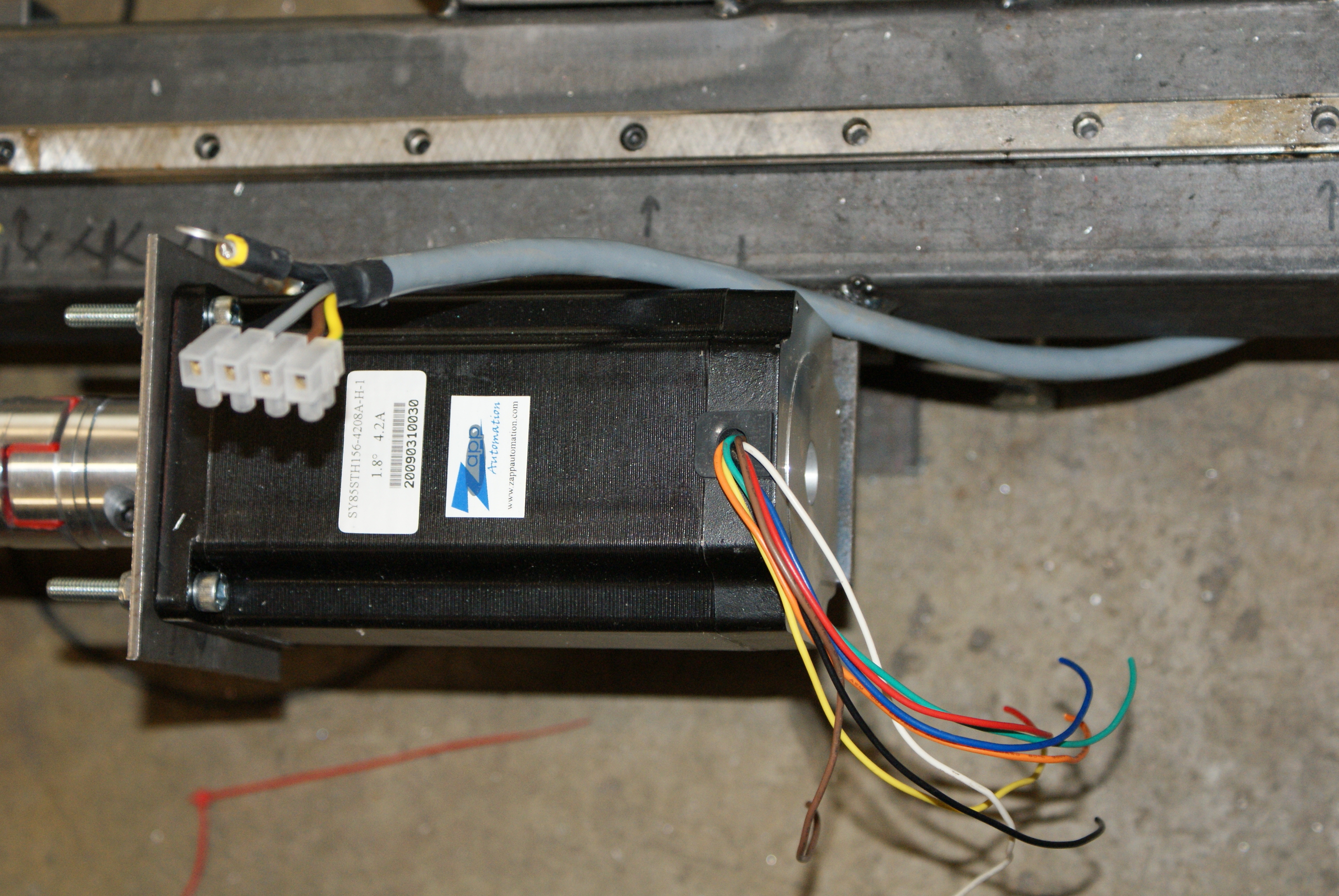
I then wired the motors into the drivers - I'll connect the sleeves to an earthing point (the other end I'll drill and tap for the ring connectors (the Z-axis has already been connected, since there is already a place where it can be connected).
The reed switches didn't arrive in time - however, I'll leave them until later. I want to get it moving!
I'll need to get a 115V supply tomorrow, so I can safely power the drivers (they can take 220V, but that's about it - with all the welding going on next door, I don't want them fried).